Serial communication

Hi all,

Is there a way to set pixel count via serial communication?

Here’s what I’m trying to achieve:

I’m working on version 2 of this project that’s meant for my kids. Given that they will be removing/adding bricks constantly, I want to find a way to enter the pixel count in settings kind of automatically. The ideal scenario would be to have an Arduino in the enclosure with PB, and when a button is pressed(connected to Arduino) it would do the following:

  1. Send command to PB to switch to a pattern with static color.

  2. Measure the current. Knowing the LED’s consumption for any given color, it’s easy to calculate how many LEDs are connected.

  3. Send that number to PB.

  4. Send command to switch to the previous pattern.

I know I’m probably asking for too much but it would be a cool feature to have:)

It’s a straight line of LEDs in the end, right?

Suppose you have the PB always sending data for all of the possible pixels (e.g. just black for the pixels beyond the current length), and put the Arduino in a little end block “magic wand”. It just has to read the decrementing-pixel-address out of the serial stream and then it knows exactly how many pixels there are. Tell your kids they have to wave the magic wand (briefly connect the end block) at the end of the brick snake whenever they change it. Or, if price is no object, put an arduino at the end of every block and reconcile “maximum address last mentioned” on the PB.

Or you could make a max pixelcount (and never change it except thru UI), and then make the ‘real’ pixelcount be a setting in your patterns. (Yes, youd’d have to modify existing patterns, to use yours). The question is how would you populate this value, since each pattern would have to be able to calculate it. If you used the sensor board protocol (documented in the docs for it), you could send a value that could dynamically change based on the number of blocks… and some way to generate serial data (so Arduino, for example). So whether you use the above idea of current measuring, or @sorceror’s idea of a smart end cap, or some other method, you just need to serially send the value back to the PB via the existing sensor board input as a value it’ll be polling for anyway.

If you swapped the Arduino for a wifi-enabled chip like the ESP-01S – it’s the same ESP8266 MCU that’s in the v2 Pixelblaze, but in a pico package – you could send a websocket message to the Pixelblaze to change pixelCount in the settings. Or if you don’t want to learn another platform, just use an ESP-01S as a wifi adapter for the Arduino…same exact same.

To find out what the message would need to contain, open up Developer Tools while the webbrowser has the Settings page loaded, and look at the websocket message traffic while you increment and decrement the number of LEDs.

I think, rather than try to count ws2812 data bits to figure out how many pixels, I’d try something like running a separate voltage-carrying wire through all the blocks, with a resistor that knocked the voltage down by a specific, easily distinguishable amount per block.

That way, you might be able to use the Pixelblaze’s analog input to read the voltage and calculate the number of blocks pretty easily. Dynamically changing pixel count is another story. Possibly better to just adapt a few custom patterns for these blocks.

1 Like

@sorceror some of the possible configurations are closed-loop and don’t allow any extra bricks to be connected(squares or circles for example), plus the Arduino brick would still have to be wired to the PB box, making it all accident-prone and messy. Your reply though kind of answers another question I have and would be posting in a new thread. Most of the connecting tubes split the output 2,3 or 4 times, I was thinking if there is a way to have a microcontroller in there take the incoming signal, and add 10 virtual less to every output. To make it a bit more clear, index is at say 50 when entering the connecting tube, 1st output starts at 51, 2nd at 61, 3rd at 71. I tried googling it but didn’t come up with anything meaningful. Using SK6812 btw. If you suggest that an Arduino can read the pixel address, then I guess it’s doable?

@Scruffynerf I am using an expander. If I get you right, it’s possible to use the expander’s serial to feed the values from an Arduino, correct? Could you maybe elaborate a bit more?

@pixie I really prefer a hardwired approach to the solution, adding yet another wifi board in the box is something I prefer to avoid, but if I can’t find another solution the board you suggested is super small and as long as I can figure out(google to be precise) how to do a combination of current sensing and sending messages to PB with it, I’ll go this route:)

@zranger1 Great idea but I have no pins left in the connectors for another wire, I’m already current-limited as it is. In addition to that, I’m trying to be kind of backwards compatible and be able to use the bricks I’ve already made for v1.

The problem with saving the pixel count within the pattern is that the value would not persist between resets etc-at least not until Ben adds variable saving in a future release.

Correction: I said Expander but meant Sensor Board. I’ve fixed it above

Here’s the details on the sensor board protocol, which you could make your arduino speak

Keep in mind, there is code to accept the OUTPUT of a sensor board (https://github.com/simap/PixelblazeSensorBoardLibrary). I’m talking about the opposite: you’d pretend to be the sensor board with your arduino and talk to the PB.

I think the websocket approach is likely cleaner, given your points above, but it’s an option so…
Wired serial vs wireless

Yes, definitely possible. I’ve done something like that for a client project (can’t share the code though).

I’ve also head of others doing this and sending config down as fake pixels, so the micro can get configuration about how many pixels to route. That of course would most likely require some modification to PB, or some interesting hackery in the pattern code.

You could hack that with one or more WS2811 IC controlling a signal multiplex without a micro. If you detect this control pixel (which uses no more current, yet consumes 1 pixel of data), then you could steer it by setting R or G or B to 100%.

If you have a micro in each node, it might be easier to use the expander serial protocol instead of ws2812 data, and give each node it’s own single-channel address. Then it wouldn’t matter where they were, they’d still get the same pixel addresses. You’d want to buffer the serial data for each split though to avoid reflections.

Does PB expect to get such data from the sensor board? So far in the documentation I only see mentions for the sensors, nothing related to pixel count or similar.

If you have a micro in each node, it might be easier to use the expander serial protocol instead of ws2812 data, and give each node it’s own single-channel address. Then it wouldn’t matter where they were, they’d still get the same pixel addresses. You’d want to buffer the serial data for each split though to avoid reflections.

Can you please elaborate on how to do this? Is there any documentation available for it? I must admit I’m completely out of my depth with this one, so if I go down this route I’ll have a million questions. Having individual addresses seems to be a great way to solve many issues, but I don’t get how it works if there is no feedback. How does PB understand where the nodes are placed? If you have for example 10 leds in row, then split to 2 or 3 nodes of 10 each, what’s the order, is it based on the address’s number? I guess you’d have to let the expander know how many nodes are connected, correct?

Nope, you’d have to Homebrew it to take some data it did expect and convert to a pixelCount substitute.

You’re really pushing the limits of PB here.

Looks like websocket is the way to go, thanks for the explanation.

Sorry, I meant the output expander, not the sensor board. In combination with what you are using to sense current (which might be a sensor board).

OK, without a custom micro, consider how this could work with existing output expanders.

If you used an output expander (OE for short) in each node, and used a unique combination of output channel and board address, you could have 64 unique node addresses. Each of those could be configured for a unique range of pixel addresses.

For example, let’s say you have 12 pieces / nodes. You’d need 12 OE. They are all fed off of the same data stream. On the first 8 nodes you would leave the OE addresses set to 0, and connected LEDs to increasing output channels from 0-7. The 9th through 12th nodes would be at board address 1, using 4 channels numbered 0 through 3.

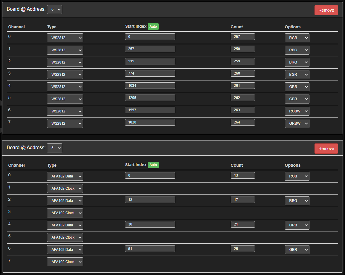
In the PB settings screen, you’d set it up with only 2 boards (one at address 0, one at address 1), and configure the channels for each node. Sure all 8 OE at address 0 are doing the same thing, but only one of the channels is connected at a time.

Let’s say to make the math easy for an example, every node is only 10 pixels long, and on the setting screen, each channel starts at the next address (as it would if you clicked the auto button).

The first node is at board 0, channel 0, and has pixel start index 0, length of 10. It can be drawn in a render when index is 0 through 9.

The next node is board 0, channel 1, and has pixel start index 10, length of 10. It can be drawn in a render when index is 10 through 19.

And so on. You’d have 120 pixels in total, no matter how many nodes were actually connected, and in any order.

It wouldn’t know where in the assembly they are. The order wouldn’t matter (to it) since they have a fixed address, and it would have the same pixel index no matter how many nodes or in what order they were arranged. You could handle those aspects in some other way, this would just be a way to get everything individually addressable and doesn’t have any inherent detection, it’s just output.

If you don’t want to buy and install an OE for each node, but have room for your own micro and lots of free time, you could adapt the output expander code or write you own client that reads the data stream and spits out a single channel for the LEDs.

It wouldn’t, not alone. You’d need some other way to detect the order, but to some extent the order wouldn’t matter in that you wouldn’t need it in order to know how to draw things consistently.

In some ways this would make it harder to detect, since turning any given pixel or node on/off changes the current draw by the same amount regardless if where it is, but you could still detect the presence / absence of a node.

I cannot fit an OE in the bricks, no way, and going for a micro involves coding skills I simply don’t have, so I’d like to investigate the possibility of modifying the signal within the connectors and changing the index(adding 10 pixels) in the forked output. Any chance you can point me to some sort of documentation or similar? I can’t find anything related to SK6812 protocol or what type of controller I would need to achieve it. I’m willing to invest plenty of time on this but I need to start somewhere:)

6 of one, half a dozen of the other. If you have a custom micro doing stuff, then you have about the same amount of work either way.

SK6812 is the same as WS2812, a series of pulses that are either long or short. 24 of these for every RGB pixel. A pause of many microseconds means the data is done. The pulse timing is brutally sensitive though.

For specs, look at any ws2812 / sk6812 datasheet.

I’ll play around and see if I can pull it off, if not I’ll try fitting 10 leds in the connector, maybe break the leds and see if the ICs still function:)

Going back to the question of changing the pixel count remotely, I went through the Websocket API docs and didn’t find any mention to it. Is it possible or not? Bear in mind I’m using an expander, so I’d need to change multiple outputs and not only one.

I wouldn’t change the pixelCount unless you can’t use another variable in the pattern for some reason. I would add something like “detectedPixelCount” and use that (it could default to pixelCount if you like).

Writing pixelCount will re-init the current pattern, and by default causes a write. Same for the output expander settings, which goes hand-in-hand with pixelCount. The map would have to be regenerated in the UI, if you have one.

1 Like

I don’t mind having to redo a map if necessary, I hardly ever use them anyway.
It’s still a bit unclear to me if it is possible to set pixels in the expander settings through web socket, could you please clarify? After putting in the new values I’d have to reload a pattern anyway, something I have to do now as well, I don’t know if it’s meant to work in this way but when I change the pixel values in the settings tab the pattern doesn’t re-initialise so I have to go to the patterns page and select it anew. I would do that easily via web socket.

Looking at the websocket traffic with Fiddler, changing the pixelCount on the settings tab sends a single websocket message containing the JSON string: {"pixelCount":100}. If you have an outputExpander configured, any change to the expander configuration sends both the pixelCount message and a binary packet with header values 09 05 containing the updated outputExpander configuration file.

The outputExpander configuration file (also available from the Pixelblaze’s webserver as http://pixelblazeIP/obconf.dat) has a header byte of 05, followed by a 96 byte table for each output expander (8 channels * 12 bytes/channel).

For example, defining two expanders like this:

Results in a table like this ((initial magicNumber of 05 omitted to make row data structures line up better):
image

Which can be decoded using the data structures found in the outputExpander source code as follows:

Where:

  • addx|chan is a packed byte (addx:5|chan:3) combining the expander address and the channel index
  • ledType is an enumeration with 0=‘notUsed’, 1=‘WS2812B’, 2=‘drawAll’, 3=‘APA102 Data’, 4=‘APA102 Clock’
  • numColors is either 3 (for R/G/B) or 4 (for R/G/B/W)
  • colorOrder is a packed byte (R:2|G:2|B:2|W:2) containing four 2-bit numbers indicating the order in the colors appear (0 = first, 3 = 3 last). The possible permutations are: 0x24=‘RGB’, 0x18=‘RBG’, 0x09=‘BRG’, 0x06=‘BGR’, 0x21=‘GRB’, 0x12=‘GBR’, 0xE4=‘RGBW’, 0xE1=‘GRBW’
  • pixelCount is the number of pixels on this channel
  • startIndex is the first address in the range to be directed to this channel

As @wizard says, updating the pixelCount will save the new value to the flash chip which can be written a limited (though reasonably large) number of times, so you don’t want to do it unnecessarily; however frequently you calculate the number of pixels, you’ll only want to save it back to the Pixelblaze if it has changed.

1 Like

Wow, @pixie going all RE on the files! :clap:

FWIW, thats the file format revision number/code. 5 is the current version, but older versions of PB might have a different format.

The “not used” is the uint32_t frequency for output clocks, which is currently hard coded for 800khz. The expander almost has support for this, and would fall back to 800khz if any of its channels were ws2812. The new chips can handle 4mbps data streams, but I didn’t get auto baud detection working in time. At 2mbps of input data, it was kind of a mute point as 2+ channels of APA102 @ 800khz can keep up with the data input.

2 Likes