I am super new to electronics and need help making sure my setup is correct so I dont damage my lovely equipment.
In summary I have:
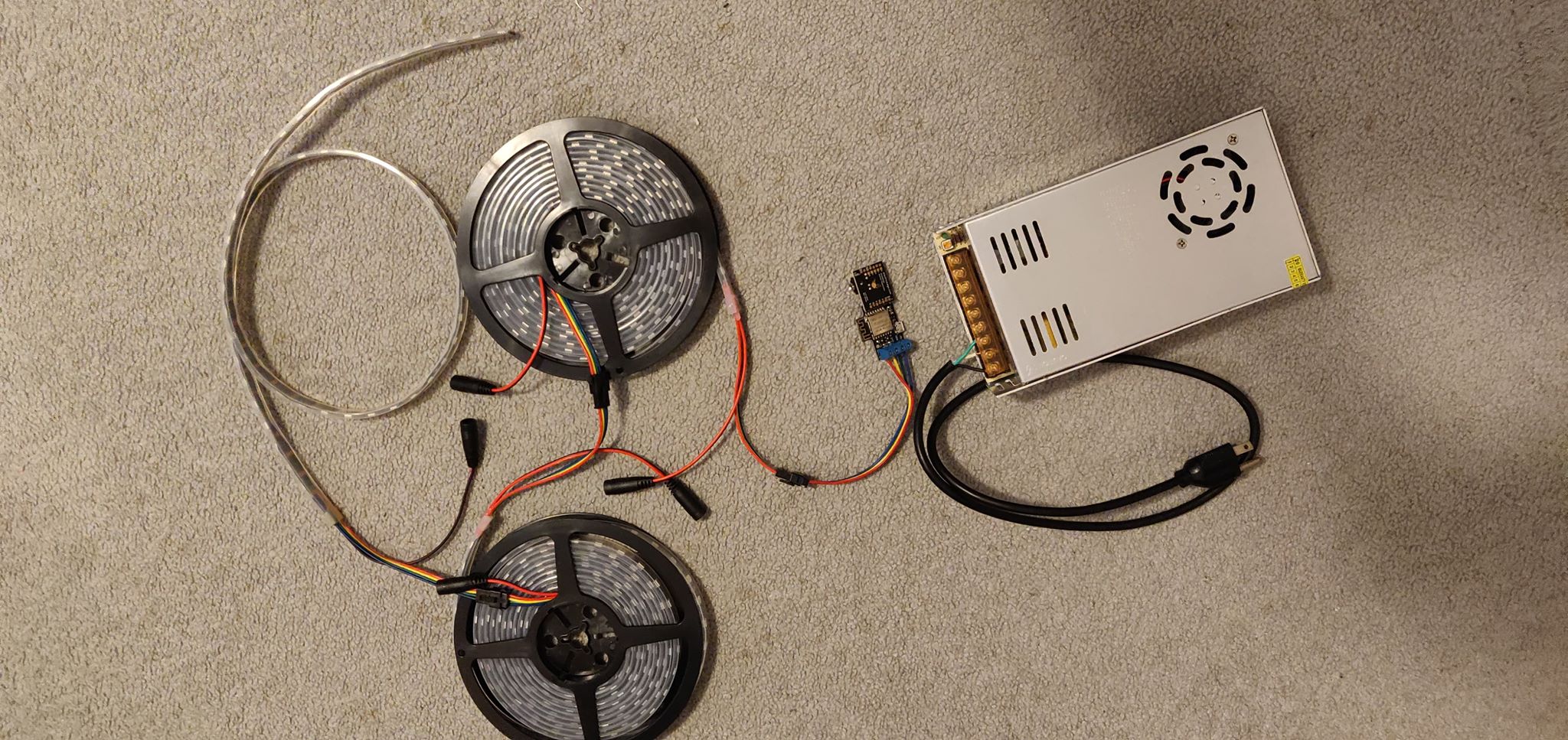
9m of APA102 LED Strip (amp requirement calculated at about 10 amps)
300W 60A Power Supply (AC 110/220V to DC 5V)
I intend to do some power injection so that I do not encounter voltage drop. I think I equipped my system to handle full brightness/white/frequent pattern shifting
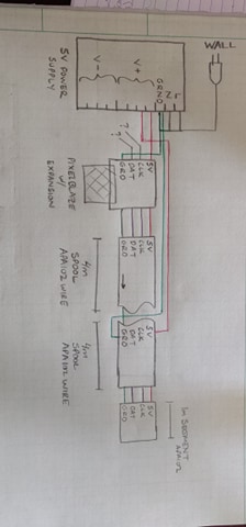
Attached below is my current wiring diagram
For power injection, I will solder or gator clip an AWG 18 Cu from the 5V terminal on the strip to its own V+ screw on the power supply per 4m segment. Is this correct?
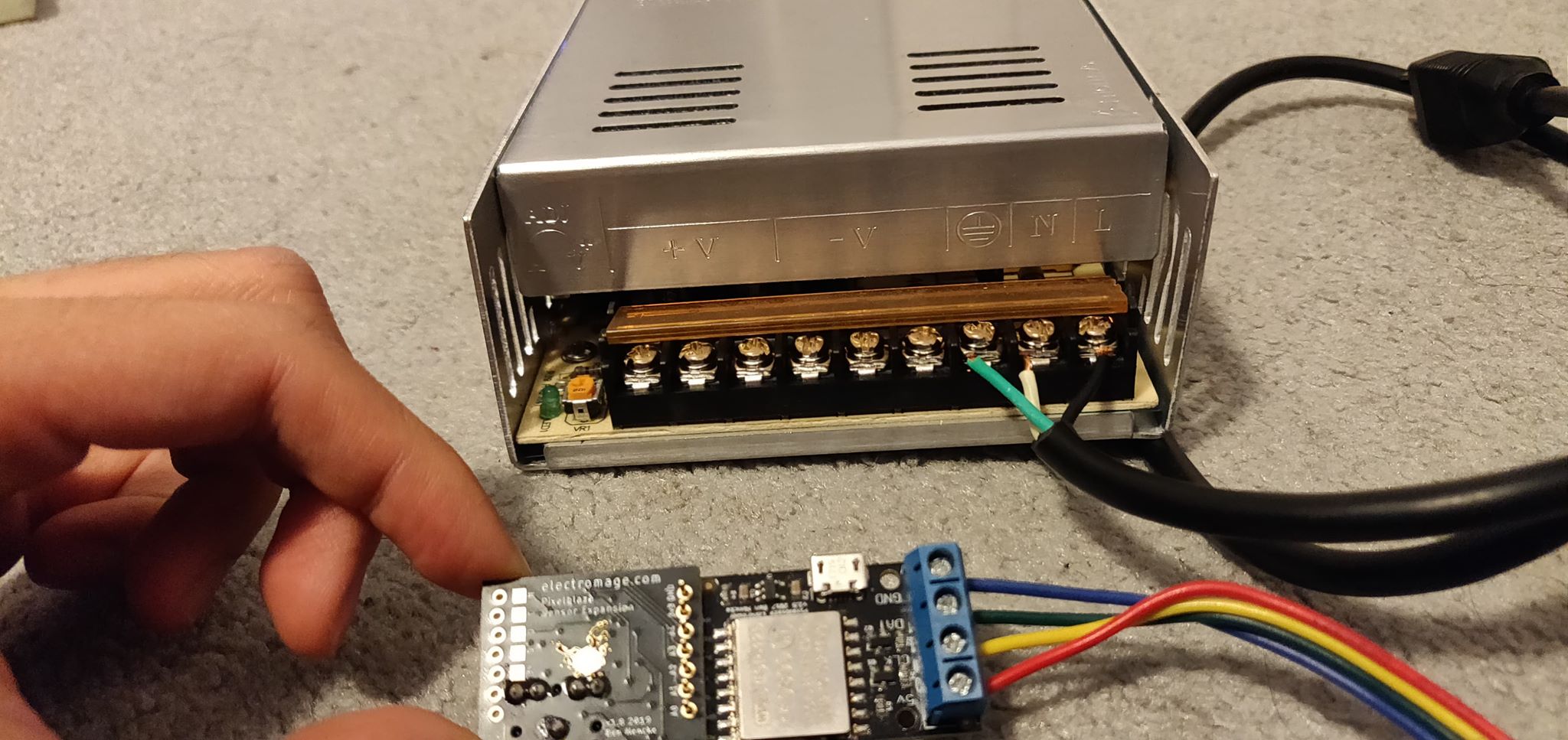
Will the strip, the power plug, and the pixelblaze controller all share a ground screw? I would think so but wouldnt that make that ground screw super busy? I worry I may run out of room in the power supply’s ground terminal and as a result, the screw doesnt hold the wires tightly.
For the pixelblaze controller itself, I understand that the red 5V wire should go to the V+ terminal on the power supply. What do I do with the remaining CLK and DAT wires? Do they go on the V- terminals of my power supply? Or do they just hang freely for not being used?
I have AWG 18 Cu wire and need to ground the pixelblaze controller, which uses AWG 20 Al wire. Can I combine the two types of wire? I tried feeding the 18 Guage to the ground terminal of the controller but it wont fit properly so I think I might end up simply splicing leftover 20 guage and attaching that to the ground screw. Is that correct?
Finally, I intend to have the expansion connected to the pixelblaze as shown. I did not want to deal with clearances by stacking them. Is it safe to directly solder as is? Can someone show me how they soldered theirs?
Ive learned a lot about electronics just from attempting to put this all together. I just want to make sure what I have currently is safe and feasible.
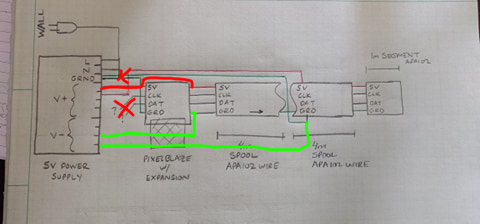
Use V- for GND for the LED circuit, the GND on your power supply is power ground (from the socket). While they may be connected (maybe not!) there’s a lot more room for power distribution on the V- terminals.
In other words, the earth ground on your power supply should only be connected to the plug.
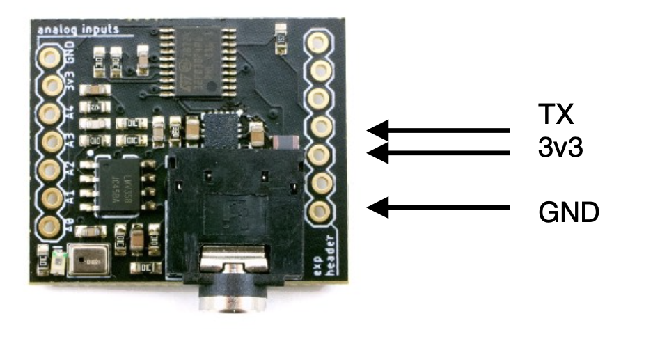
The sensor board is on backwards, that is the analog inputs (for extra sensors). The expander port is on the other side nearest the audio jack. Check the pin labels, and the instruction sheet for possible mounting options. Let me know if you don’t have that, I’ll post a copy!
Alligator clips are iffy for power distribution, I would solder direct or use screw terminals.
The clk and dat lines from Pixelblaze go to the LEDs. There is a single set of these, with 2 internally connected headers (they are the same), in a 0.2" spacing for the screw terminal, or a 0.1" spacing for pin headers. There isn’t an extra set going off to the side.
Since you have the screw terminal attached, I’d use that. Wire V+ and V- to Pixelblaze’s screw terminals - in addition to the 4 colorful wires you have now for the JST connector. That will power Pixelblaze and the first strip.
You can power the strips through the 2.1mm x 5.5mm jacks (2 wires, red + black). If you don’t want to use the jacks, you can cut off the receptacle and solder directly with their wire leads.
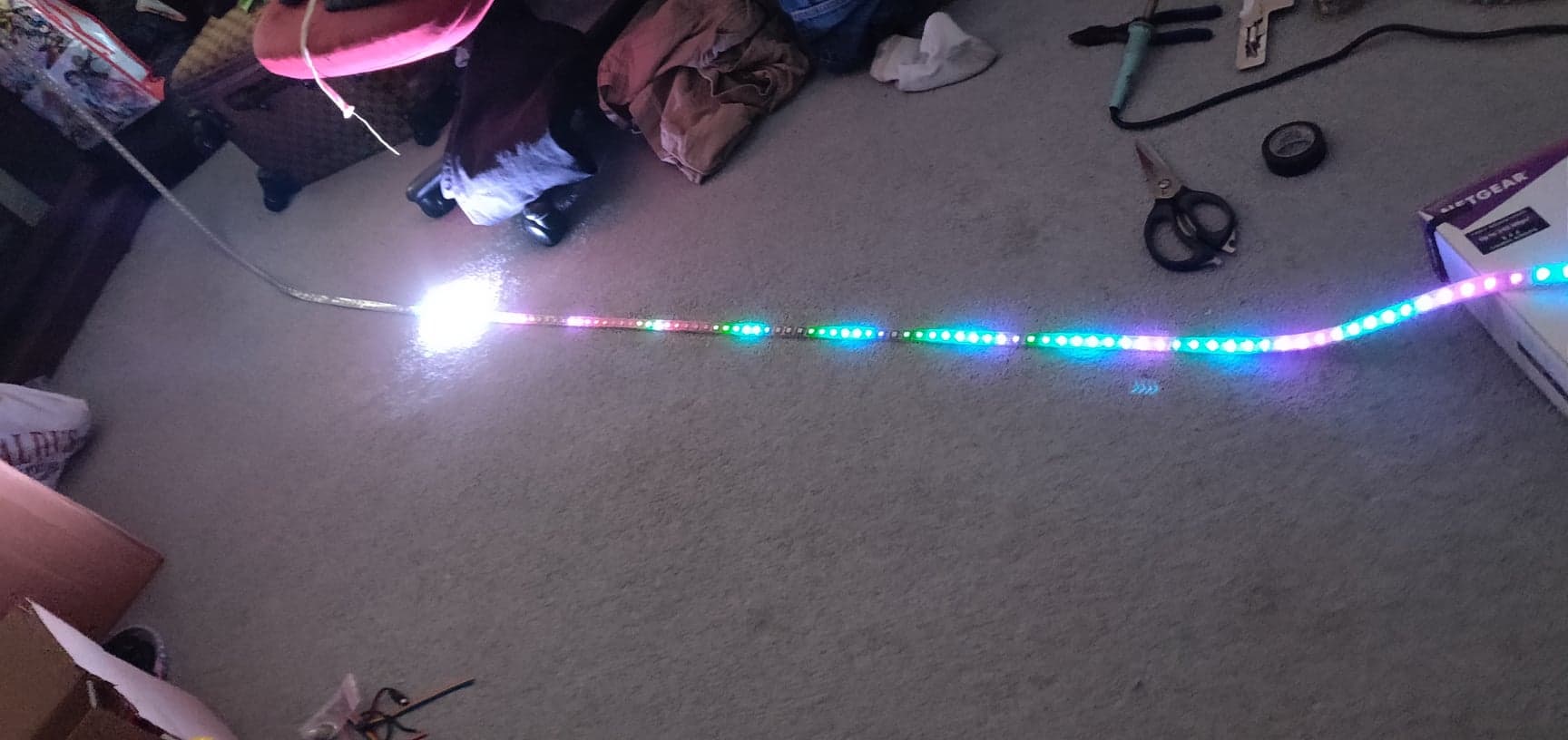
Sorry It took me so long to reply. Yes! Your guidance did work and I passed the smoke test!
However, the lights only go up a little past the first meter and its endpoint is white at max brightness. To me it feels like all the current is dissipated here ergo why it’s white and max brightness. Is this fixed with more power injection?
Hi @PixiStyx,
Did you set the total number of pixels? Defaults to 100, and the trailing white is common if there are pixels past on the data line (a few pixels worth are flushed out to make sure they all grab the data).
By the way, if power is an issue, you’ll see colors shift toward red and dim.