On the v2 and v3 full-size board are some solder pads on the back like IO21, IO19, etc.
I tried searching, and I can’t recall if I asked this elsewhere, but perhaps I’m using the wrong words. Is there an example somewhere I can reference to write some code that…
makes a pad go “high” or “low” like a pin on Arduino? Idea being I load a certain sketch, and rather than drive LEDs, all it does is make the pad go +5v
advances to the next / previous pattern when an IO pad is shorted to ground or Vcc? or am I to solder my switch in parallel with Pixelblaze’s onboard button?
@jpm,
Same API as Arduino. Look at the docs for pinMode, digitalRead, and digitalWrite. You can also use the touchRead API for capacitive / proximity sensing. On the V3 there is analogRead as well.
All IO on both the V2 and V3 are 3.3V, with the exception of the analog input pin on V2 which should be 0-1V.
Yes, the button signal which is also available as solder pads directly on the reverse of the button can be used to advance the pattern. To drive that signal, short BTN to GND momentarily. This is indeed in parallel with the button itself, so don’t drive this high with a strong signal, as the button will short it to GND.
@jpm, I used to read the docs and schematics and wonder if I should pass in a symbol like GP4 or IO21, or the ESP pin number seen on the schematic… But it’s just as simple as you’d guess. If you want to read IO21, use digitalRead(21).
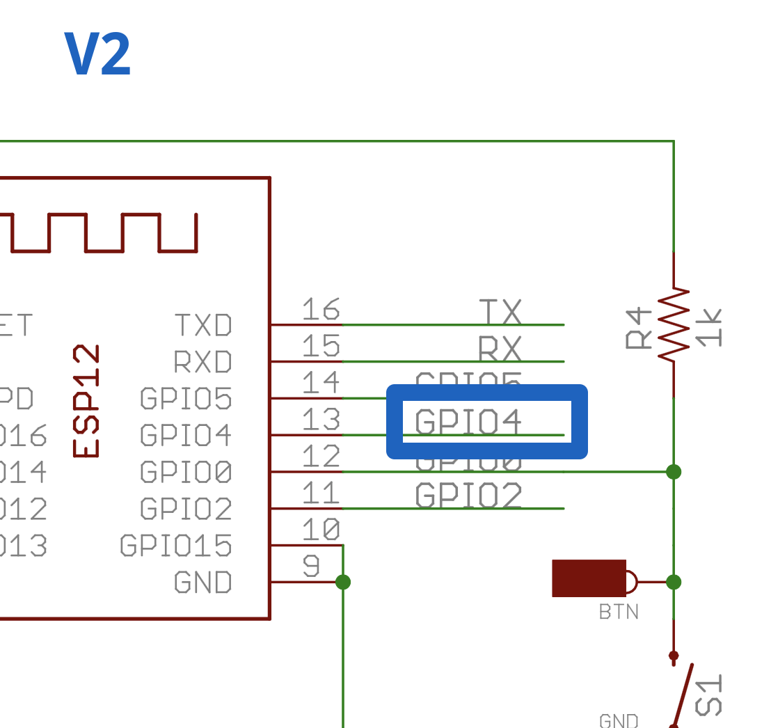
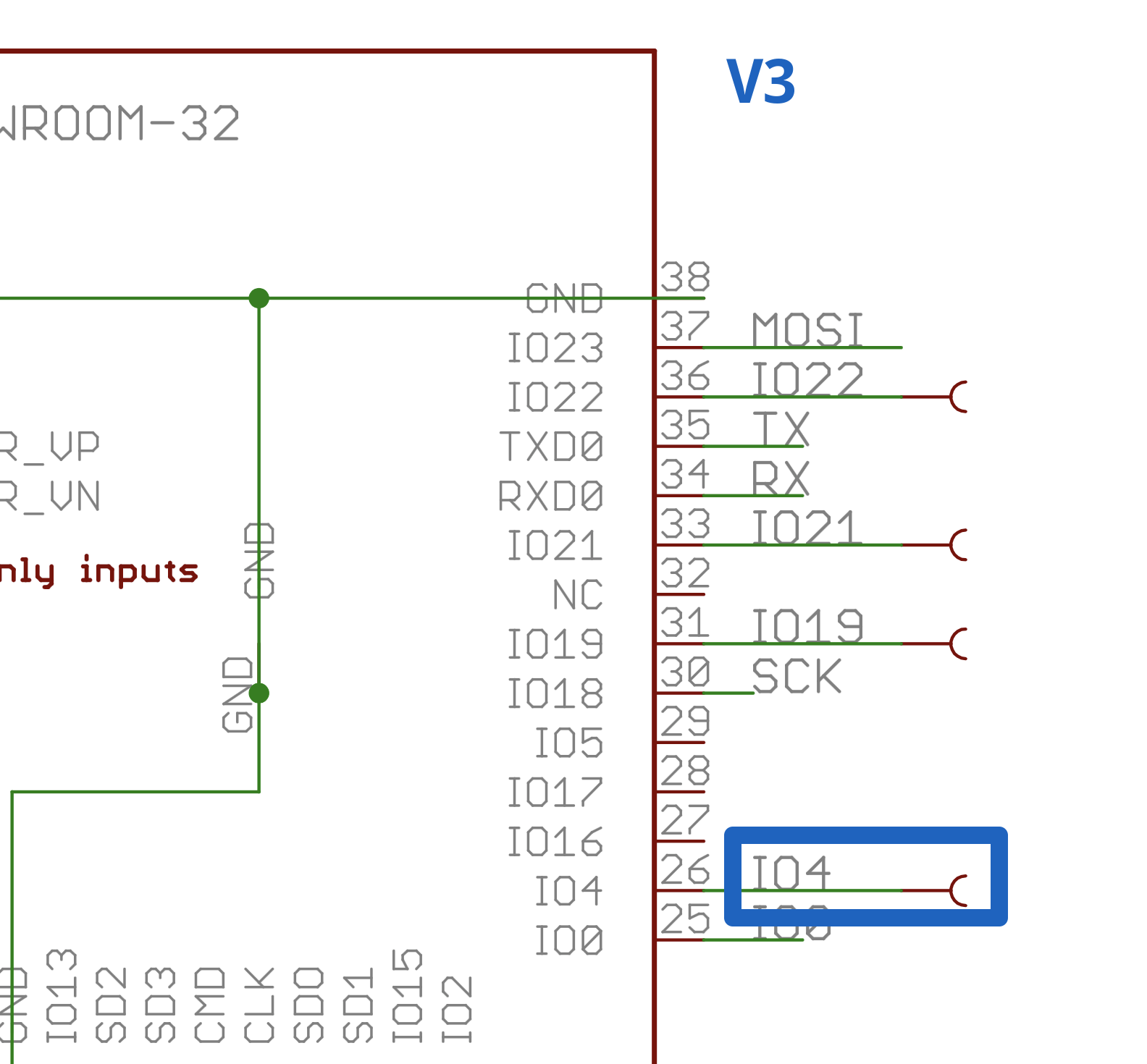
For example, Pixelblaze v2 has a pad labeled “GP4”, and v3 has a pad labeled “T0/IO4”. This code is what you’d use:
var varible
pinMode(4, INPUT_PULLUP) // Or INPUT, INPUT_PULLDOWN, etc. See docs.

export function beforeRender(delta) {
  variable = digitalRead(4)
}
This code would correspond to these parts of the schematic:
@Scruffynerf JP1 is WS2812 support (it should be labeled on the board). If you are using a clocked LED like APA102 or WS2801 and need 1 more GPIO you can cut the jumper and use GP2. The output expander also requires the jumper to be in place.