Timing of a cheap strand?

As discussed in Concentric Rings/Circle Mapping

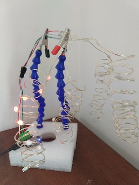
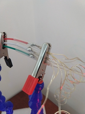
I found a very inexpensive set of 200 “fairy wire” addressable lights. I took the strand and attached it to my PB.

  1. the 3 wires are V+, G, Data. NOT V, D, G as usually found. I confirmed this.

  2. it’s RGB order

  3. perhaps it’s the 200 pixels, without added power at the far end (that’ll be my next trial but this was a quick and dirty setup), but it seemed VERY sensitive to timing:

It seemed to prefer 333 and will light them all, but pixel 1-4 are inconsistent with pixel 4 acting up most often (so in KITT pattern, it’s light constantly with RGB flickers), and if I change timing to slower um faster (286), it then fails to light everything, so I think 333 is right. Faster, um slower than 333 lights up way more junk, so that’s out.

[Thanks Wizard for pointing out it’s slower not faster… My goof]

it works at 333 with just Pixel 4 “wrong” (1-3 are fine) in KITT (modify timing line from 800 to 8000 due to #of pixels)

But if I change to “Example Color Hues”, then pixels 2 and 3 are “hot flickering” but 1 & 4 are fine… So it’s not consistent on all patterns.

Ideas?! Honestly I can live with 3-4 pixels (mostly #2-4) that misbehave right at the start of a strand, easy to just hide those, or color them black. But would be nice to figure out why? Pixel #1 (well 0, really) is usually fine and behaves correctly.

IMG_20201114_121917394|666x500

Hope you can figure these guys out – I’d love to get a strand or too as well.

While we wait for the real EE folks to weigh in, can you hook the original controller up to a logic analyzer and look at output timing and voltage? It’s pretty easy to spot and measure the important elements of the WS2812 protocol. Here’s the description I used to build the reader for PixelTeleporter.

https://wp.josh.com/2014/05/13/ws2812-neopixels-are-not-so-finicky-once-you-get-to-know-them/

If you don’t have a logic analyzer at hand, it might be interesting to hook up a known good WS2812 LED at the front of the strand and hook that to the Pixelblaze. It’s possible that these guys use a super discount chip that doesn’t completely implement the protocol. Sticking a “real” one at pixel 0 might normalize timing for lights further down the strand.

1 Like

Yeah, I can do that, including just a single pixel, have a pile of them. Good idea.

I have some coming next week to check out.

Btw 333 is slower than 286. Those are nanoseconds. You can hack different timings by sending values not otherwise listed in the ui. The underlying value is bit timing in hz.

I’ll try to expand more on that later…

2 Likes

Cool! I didn’t know you could enter custom timings. The numbers in the UI are for zero/one?

1 Like

Here’s how to hack your way to custom timings.

When you select 333/667ns in the UI, this is sent over the websocket to tell Pixelblaze the change:

{"dataSpeed":3000000}

That uses a bit timing of 1/3000000, or about 1/3rd of a microsecond, roughly 333ns.

Likewise, when you select 286/571ns, it sends this:

{"dataSpeed":3500000}	

Which is 1/3.5 microseconds.

These translate to zeros or ones in the WS2812 protocol. Zeros have a single bit time and for ones, it is doubled.

You can send almost anything you want, but you may have mixed results and might cause instability if you go too far off. For example, if you go too low, you risk taking forever to send out pixel data, and that might make all kinds of things unhappy and unresponsive. Perhaps setting it to 10 pixels or something for initial experimentation would be wise.

To send a custom value, you can use one of the helper functions used in the interface, by opening your browser JavaScript console and entering something like this:

sendFrame({dataSpeed:3500000, save: false})

“Hey wait, where’d this ‘save: false’ stuff come in?” I hear you asking. Most config settings save by default, but there’s a flag that can be set to override that, and if you do end up with a bad value that breaks things horribly, its best that it isn’t committed to the config permanently. You can take that out (or set to true) once you are certain it’s working.

Of course if you save a value the UI doesn’t support, it won’t know how to update the settings dropdown when you reload the interface.

For those curious, I’ve open sourced my driver here:

The version used in V2 has a fast, buffered mode and a slow unbuffered mode.

It is based on a similar approach used in some other WS2812 drivers. It uses a hardware UART (serial port) in the esp8266 because it provides a hardware buffer, packing 2 bits per byte sent to the UART. The 128 byte UART buffer can store 32 bits of WS2812 packed information, enough for an entire RGB or even an RGBW pixel!

The original WS2812 protocol is quite picky, and will glitch if there is too much of a delay between bits/bytes. EmpIrically, the latch time was found to be as little as ~6 microseconds! Thats a problem on systems like this that borrow CPU time to handle WiFi things. Later WS2812b and WS2813, WS2815 and possibly many clones improved on this by raising the latch time to 250µs.

The unbuffered option stretches out the bits to give more time to render pixels, but complex patterns may take too long, causing glitches. Thats why there is a buffered option, which can also run a faster data speed by default, but can’t render pixels while data is being streamed out like the unbuffered option can.

The utility of the unbuffered version is kind slim, so most of this configurability isn’t in V3, which uses a fixed timing that has broad compatibility, but runs at a fixed speed.

5 Likes

@wizard, thanks for writing this up. It’s one of those “easier to write the code than to write the documentation” things (of which there are many). Much appreciated! :slight_smile:

2 Likes

Stranger and stranger:

Ths guy claims despite setting up a set of these (which he got on eBay) as a Y, these maintained unique “locations”. Not behaving like normal ws2812s, but some new clone.

If he’s right (and not sure he is), this is a whole new take on addressable LEDs… And would make weird wiring (allowing forked data lines to work as one strand) possible.

Looking forward to you testing these.

@jeff did you notice anything weird on your string (s)?

1 Like

This is really interesting! Being able to splice together strings and still maintain individual addresses would really be handy. If it is a clone, what were they trying to overcome - or why make the change to use with these specific lights? Excited to hear what you guys find out.

Indeed, very interesting! A bussed addressable pixel may simplify wiring for strings. The other WS2812 strings I’ve seen look like they solder to 4 wires and cut one out. I think they alternate flipping DIN and DOUT between 2 module designs, see below:

Having 3 contiguous wires would appear to simplify string manufacturing/soldering by removing the 4th wire and any need to cut anything. But it adds another cost - they’d have to keep track of which pixel went where (you wouldn’t want 2x of pixel #5), or have programmable circuitry in each LED which would add expense and other manufacturing headaches.

Perhaps they do have a one-time-programmable memory or “fuse” that is set during manufacturing. Those can be less expensive to implement, but again would need more processing during manufacturing. LEDs can be turned into detectors, so you could have an unprogrammed chip read addresses from the bus and wait for a flash of light to indicate which bit of address data was for it. I’m just guessing here though.

There are other tricks that could be used to detect distance from the controller and dynamically set ID, but those seem advanced.

Some other 1-wire bus protocols have large unique addresses and can do bi-directional communication and device discovery, but again that seems pretty complicated.

My understanding is that the IC design for WS2812 controllers is simple (24 bit latching shift register takes in the pulses, 3x 8-bit PWM controllers, 3x constant-current drivers, output pulse driver), and while transistors tend to shrink over time allowing more to fit in small spaces, I’d expect the first debut to be more expensive.

I’ll have one in hand to poke and prod Thursday…

1 Like

@Scruffynerf, do you have some high res close up photos for us to ogle in the meantime?

2 Likes

Yes, I’ll take some photos and I’m going to play with some forked data as well…

Yes, I was going to buy some of the design you added a photo above… Call it 3.5 wire for short. That’s why I was confused at first by this 3 wire design. That it is explicitly not the usual VDG design is surprising but does seem to say it’s not just a ws2812, if only because why change that layout?

I just ordered a similar fairy string of 50 which is explicitly “rgbic” (Govee is pushing this name) (this one has a Tuya controller, Alexa/etc)… But those RGBIC strips all seem to have an external IC chip, so I’m still confused how this stuff works. Ah the fun of discovery!

I’m very pleased that it does work with PB (and I’ll assume WLED/etc, that’s on my list to try but I have no reason to assume it won’t)

@Scruffynerf,
RGBIC, that looks like 3 LEDs per pixel 12V WS2811, with some unrealistic photoshopping.

1 Like

Three LEDs per controller IC, all showing the same color. https://automatelife.net/govee-dreamcolor-rgbic-led-strip-lights-h61631a1-review-no-hub-required/

Yes, I realize the rgbic strips are essentially a ws2811s (I think that’s the right one)… But that doesn’t describe these copper wire ones.

Anyway, we’ll see what’s what. I’ll be doing some testing and sounds like others are too

So I can now confirm these DO have some sort of “memory” for their location. I cut off 10 from the end of a strip of 200, and cleaned the ends (lighter to burn off lacquer coating on wire, use sandpaper so you see shiny metal), soldered to a connector, and hooked up.

With a single normal pixel first (which wasn’t RGB, it was GBR, but…), these still insisted on being 192-200(I couldn’t get the last pixel to light correctly, even telling PB I had 205+ pixels. Either it was off or it would do just red).

With NO pixel in front, these behaved perfectly… told it 200 pixels, and it was 191-200.

I’m going to try some Ys next.

These are cool, I see so much potential.

First Y works… Independent lights despite the Y of data and power. Wow. Photos soon. But seeing this blows my mind. It’s a whole new ballgame for led wiring addressables.

@wizard’s volumetric cube was done with a pile of expansion boards to ensure each strand didn’t need to run a data line back up to the next… This removes the need for all of that. A single expansion board could drive up to 8x200 (1600! Or more than enough for a 11x11x11 cube!) Lets keep it simple and say 10x10x10… 1000 pixels.
Connect data and power for 15-20 strands of 10 pixels, all soldered together at one end, just 3 wires to many. Layout and map it all, and done.

1 Like

@Scruffynerf
Interesting! Have those close up photos?

What happens when you combine 2 independent strings of 200? Is the data line electrically connected throughout, as a bus, or chained like regular WS2812?


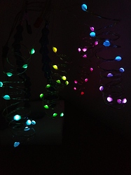
My test setup: 4 strands of 10 (curled for ease of control), all on one connector.


Excuse the sloppy soldering

Low exposure so you can see each pixel is different and it’s absolutely not mirrored

No, I have not tried putting two strands together, but I’m going to guess they won’t behave well. Until we understand how it retains “position” info

I’m glad I bought 6 sets, as the price at Amazon has gone up $2 already. (10% increase)

I’ll look at doing some video, the stills don’t do it justice.

1 Like

Uploading video now to YT. Btw, 333ns works fine so far. Perhaps length vs timing is an issue with long runs. TBD.

1 Like