It’s not going to be easy to hack into pattern code, but I can add an option in the next version.
Which LED strip did you see these on?
Yeah, the coding is giving me massive headaches because I haven’t done algebra this complex in a while.
I think I read in another post about how you choose the value of w. Please let me know if I’m right. We’ll use rgb(0.7, 0.5, 0.2) as an example. You find the smallest value, and you set that to be the W value. Here that’s the blue value, 0.2. You then subtract that value from the three colors, leaving us with (0.5, 0.3, 0.0). So you end up with the white LED at 0.2 to substitute for the amount you took out of the other three, turned off the blue because it’s not needed, and reduced the red and the green by the same amount. The white LED takes as much of the load as it can, and the color LEDs are only used for the remaining color. Is that correct?
I’ve confirmed that what happens on this strip is when it’s set for GRBW is:
The input for R is still output R. (1,0,0 outputs 1,0,0)
The input for G controls the W value directly (0,1,0 outputs 1,1,1, all white no color)
The input for B outputs to G (0,0,1 outputs 0,1,0, pure green)
So the only way to get blue is to have all three inputs be the same (greyscale), which is normally how white would work. So 1,1,1 outputs pure blue.
I used GRBW because at least on that one the red matches.
The fact that W is derived, THEN switched with another non-derived value is what’s making the coding so hard.
This is the LED strip I got. I really like this one because it’s 12V for fewer power supplies, and has the RGBWC for truer whites and more total light. I think adding support for it would mainly just require a way to specify the correct order in the Settings, either explicitly or a way to swap the W with another value like Aircookie does it. I think a lot of people will be using these WS2814s going forward for large projects where it’s good to have fewer power hookups but they need the full RGBW spectrum.
The project I’m doing now is a reflected light dome ceiling for the yurt I live in. I’m gonna have the strips on radials between the roof rafters bouncing down off the white ceiling. The main application is to duplicate the effect of the sun tracking across the sky, with the possibility of extending the day in the winter. I have really bad SAD and a much more primitive setup has already been a huge help.
I’m happy to try a test build of the firmware when you’ve got something. Thanks for looking at it, and for creating PixelBlaze! We use it in the Austin Burning Man/Flipside community a lot, including on our effigy this year.
I’ve got a working kludge for backtracking the correct values to input to rgb() . In order to set the blue value, you have to add the desired amount to all three numbers, which can obviously overflow the 1.0 limit pretty easily. I added a few different modes to handle that, including just dividing by two (half the power, but total consistency), erroring out, or dynamically scaling just the offending operation back down to fit (relative colors are correct, but absolute colors vary.) It’s pretty ugly, but for now it works. I still haven’t figured out the algebra, which would have been much faster and easier, but I think having to use the min function, plus the special case of all the values being the same, might have actually made that impossible.
Looking forward to a built-in fix, but this is enough for me to continue my eval of these new WS2814 LEDS.
I’ll post the code here once I’ve cleaned it up a bit when I’m less hacked out. ![]()
Here’s the dirty code for public consumption until I can clean it up:
// Written by Scott Mauer in December 2022
// This code is designed to remap a Pixelblaze 3.0 Standard using the GRBW color mode to work correctly on a WS2814.
// When used directly, the Red input stays red, the Green input directly controls the white LED, and the Blue input lights the green LED.
// To make light the blue LED, you must add that desired value to all three other colors. If that sum is over 1.0, it won't work correctly.
// I've added several overflow modes to handle that situation.

// I've posted on the forum about it, and Ben has already heard my plea for help.

export var m
export var rr
export var gr
export var br
export var stopstate

export var stoprr
export var stopgr
export var stopbr
export var overflowbehavior=3

export function beforeRender(delta){

   // This is where we set the desired rgb inputs
  var r = .7
  var g = .7
  var b = .7

  // First lets find the minimum of r, g, and b

  m = r
  m = min (m,g)
  m = min (m,b)

  if (r == g && g == b) { // Greyscale only, set only gr
    rr=br=0
    gr=r
    stopstate = 1
  /* Not needed, handled below in stopstate 3

  } else if (b > 0 && r == 0 && g == 0) { // If we only want blue, we need to set all three the same
    rr=gr=br=b
    stopstate = 2
  */

  } else {


    var w = m // What the PixelBlaze will decide the four values actually are
    rm = r-m
    gm = g-m
    bm = b-m

    // So now rf, gf, bf, and w should be set how PB *thinks* it should set the LEDS

    // So the question is "what do we put into the rgb call to get what we actually want?" This is the Reverse, or r value.
    rr = rm + m +bm //
    gr = m + m + bm
    br = gm + m + bm
    stopstate = 3
  }

  // The fact that we have to add the blue value to all three color inputs means it's easy to overflow the 1.0 max. These are some
  // strategies to deal with that until Ben provides us with a built-in fix.
  if (overflowbehavior == 3) { // Just divide everything by 2 so absolute/2 is preserved
      rr /= 2.0
      gr /= 2.0
      br /= 2.0
      stopstate = 6
       }
  else if ( (rr > 1.0) || (gr > 1.0) || (br > 1.0) ) { // We've overflowed our buffer!

    if (overflowbehavior == 1){
      stoprr = rr
      stopgr = gr
      stopbr = br

      rr=gr=br=0
      stopstate = 4

    } else if (overflowbehavior == 2) { // Dynamic scale if overflowed. Relative values are preserved, but absolute ones are not
      mx = max (max(rr,gr),br) // find the culript
      rr /= mx
      gr /= mx
      br /= mx
      stopstate = 5
    }

  }

}

export function render(index) {
  // Pattern is set to GRBW
  // When I do this,
//  rgb(1,0,0)
  // I get what looks like full red (correct)
//  rgb(0,.1,0)
 // I get what looks like full white (green = white)
//  rgb(0,0,.1)
// I get what looks like full green (blue = green)
// rgb(.1,.1,.1)
// I get what looks like blue, but with a little bit of the white LED it up.
// Q: Is there a way to get only blue with no white?

// Check out this weirdness
// Start with this
// rgb(0.1,0.0,0.1) (yellowish, as expected for a combo of red + green )
//...but then try this
//rgb(0.1,0.1,0.1)  // (but now red and green turn OFF, and instead we get a dim blue with a little bit of white)
rgb (rr,gr,br)
//rgb(0,0,1)
}
2 Likes
PixelBlaze firmware is not open source? I’d love to get these strips running as well. The white seems a lot brighter than what I could do with BTF WS2815.
It seems like one could adapt the open source Ws2812Adapter here
to support the new strips, but I don’t see a way to replace the running lib. I’m probably not the first one to ask, which is why the offline loads have taken on the file extension stfu ![]()
I think nobody has ever stuck white anywhere but at the end before this… and so an if(hasWhite) was just crammed in at the end of the bitfield for this entire line of WS28xx protocols, until now.
Hey @Sargon151!
Ha, this file extension makes me laugh every time I see it as well. It actually stands for Signed Transfer Firmware Update.
Wizard will likely include WS2814 support in an upcoming release. Based on historical release cycles, I’d estimate 1-3 months.
From what I’ve read on the forums and my discussions with Wizard, the company is concerned about the cost of supporting people experiencing problems on clones or forks, as well as the ongoing commercial viability (and quality). I watched this tragedy happen to the ArduPilot boards.
He’s talked about licensing before here.
You can see the list of components and peripherals that are open-source on the github readme. It includes the open source drivers he’s released for the three major pixel protocols. In fact, I think I see some color order and hasWhite stuff in the WS281X adapter (also see this line), though my C++ is not strong enough to look through this and know if someone could essentially contribute WS2814 support.
1 Like
Despite having been shipped the wrong LEDs from China first (TM1814s) and having to re-order, the rest of my WS2814s will be here in a few days, so I’d love to see this addressed soon. Since the only difference is the color order, it should be a 3-5 line fix.
It’s interesting that some of the converter code is open source. I’m an embedded engineer with the chops to mod that code to work, and would be happy to share the results with the community (as I already did with my graceless hack above), but I’m not clear how the open source part could be combined with the proprietary part for testing. How would that work?
1 Like
As long as method signatures are not modified, with a little luck, you could drop in a shared object file (.dll, or .so in this case) and replace just the code in that file, but without seeing how the pixelblaze project is laid out, this is just conjecture as it relates to its firmware…
Also, I think you’ll want to have it selectable in the Pixelblaze app’s Settings page (under color order or pixel type), so you’ll need @wizard for that.
If you want to get this working quickly just to experiment, here are a couple of ideas:
First, you can mislead your Pixelblaze a little…
It has no way of knowing that whatever you send out as “RGB” data actually matches what the LEDs are looking for. If you tell the Pixelblaze to send 3 bytes of RGB data to your RGBW strip, it will do so. But the strip will still be looking for 4 bytes per pixel, which means that the first byte of the next pixel from the Pixelblaze will be used as the 4th byte of the previous pixel, and on down the line.
So if you set your Pixelblaze to an appropriate RGB mode and set its pixel count (actual pixel count) + (actual pixel count / 3) to account for the extra W bytes, you can use the function in the forum post below which, given a pixel index, figures out where the r,g,b and w bytes will fall and lets you set them all independently.
Calculate your white value and call your version of rgbw2rgb() instead of regular rgb.
(The function was made to allow independent control of “W” on RGBW strips, but you should be able to get it to work for your strips just by rearranging the order of the input parameters.)
And if you’ve got a Pixelblaze output expander board handy, it does have completely open source firmware, so you can reflash it to put the W byte wherever you need it. I did something related a little while ago. Here’s the forum link:
2 Likes
Aha! These are excellent suggestions, and well timed as my LEDs have just arrived today! I ordered the muxing board and will try the 3-color to 4-color trick when I get home tonight. Thanks!
-Scott
1 Like
The end of the year was pretty hectic, but I hope to get a release with support for these soon. It would indeed show up under settings.
The good news is the output expander firmware uses a fully flexible mapping system, any color can be in any position, so any version of the expander should work once the option is added to PB. The PB direct drivers, as you’ve seen, will need a little work. Rather than hack in a special case for swapping W to the 3rd position, I’d prefer to model it more like the expander.
It’s arbitrary that they chose GRWB over GRBW or RGBW, the WS2814 datasheet lists RGBW color order, while the WS2814A datasheet has WRGB. Each channel has the same output characteristics, so they just swapped it around for that strip. That means we could see more color order variants over time.
I’ll still need to reconcile this with the user interface, the combinatorial explosion of options means there would be too many items for a single dropdown, I might just add GRWB there for now to keep it fairly simple, even if the underlying drivers will support more.
1 Like
Hey Wizard! Thanks for staying on top of this, I know things are crazy all around right now.
I used the 3/4 mapping trick to get direct control of all four colors, but would really like the built-in support to use the 3D mapping, etc., without a bunch of hacks.
I can immediately see the combinatorial problem with the color order/settings. The thing that pops to mind is to have presets for the most common ones, then have some extra custom options for 3 and 4 colors where you can just specify the order directly, like maybe a select box for bytes 1-3(4), etc, like this:
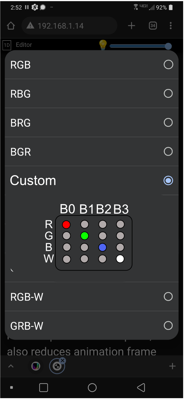
3 Likes
The btf ws2814 strip I have seems to be WRGB. Is BTF using random orders?
Turns out mine are WS2814As.

I got the Output Expander firmware hacked for my WS2814As, see the thread below for details.
So when I have the PB and the OE set to RGBW, this is what I’m needing to get the colors right.
Which is:
// Scott Mauer’s hack for WS2814s
// Set your PB and Output Expander for RGBW
// This will re-arrange the colors to be correct
uint8_t or = ch.og;
uint8_t og = ch.ob;
uint8_t ob = ch.ow;
uint8_t ow = ch.or;
So when I have the PB and the OE set to RGBW, this is what I’m needing to get the colors right. I’m not 100 sure which way to read that, it’s either GBWR or WRGB.
There may be some cleaner/less kludgy way to fix the problem, but since this is currently the only LEDS I’m working with, this works for now.
I also have some TM1814s, and now that I grok the OE firmware dance, I might try making something that works with those.
It definitely seem to me that one thing well worth doing is having a custom 4-color order option like the one I suggested above that loads the values in the PB firmware and is simply cut-and-pasted on the OE side. That way people can customize whatever they need without adding tons of permutations and code.
I think I’m seeing WRGB from that code. The pixel data is always sent in RGBW order, and remapped on the expander. The color orders are indexes are where to pull the element from in that RGBW structure.
If you configure color order to RGBW it will have ch.or = 0, ch.og = 1, ch.ob = 2, ch.ow = 3. The position of the letter zero indexed. In other words, no remapping from the packet element order.
Your code would then use these indexes:
uint8_t or = ch.og; // 1
uint8_t og = ch.ob; // 2
uint8_t ob = ch.ow; // 3
uint8_t ow = ch.or; // 0
which makes WRGB when you reassemble it. That matches what I have on my WS2814 strip!
About to use the same LEDs. Wish me luck
How much rework would it be to stop assuming pixel data is always sent in RGBW order and do some configuration-aware mapping? Do you ever bring on contributors? I get that you want to sell output expanders, but this seems feasible to me. Looks like you really love low level C++, so I will refrain from mentioning accessors – maybe assigning a bit mask on each strip type would accomplish the same with a little bookkeeping…