Upgrading my dinosaur to addressable LEDs... I have questions 🦖

Hi all, diving head first into the Pixelblaze world with a project just barely beyond my current skill set, would really appreciate some expert eyeballs on it to make sure I’m thinking things through properly. At a minimum, can guarantee it’s a spectacularly cool project!

Some background:
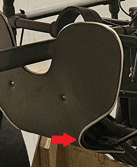
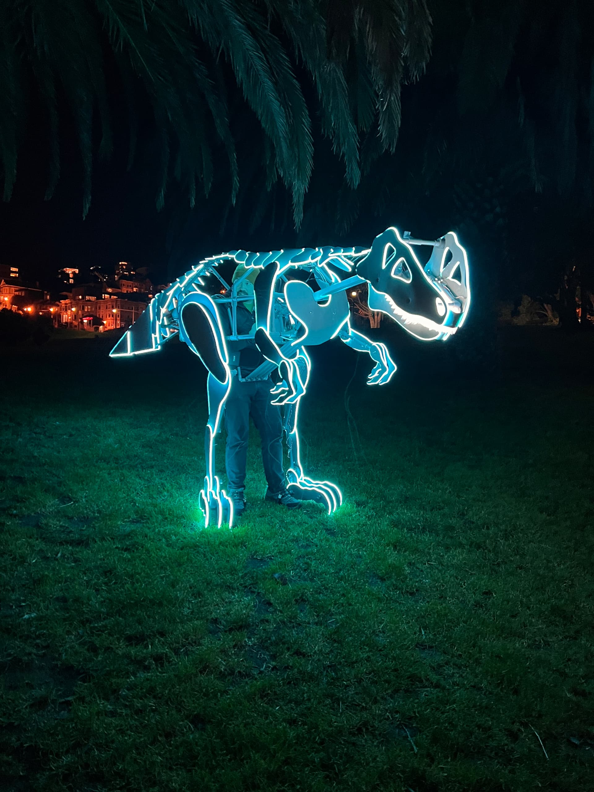
I have a delightful dinosaur puppet currently covered in ~60m of non-addressable COB LED strips, powered by 2-3 9Ah 12V batteries.

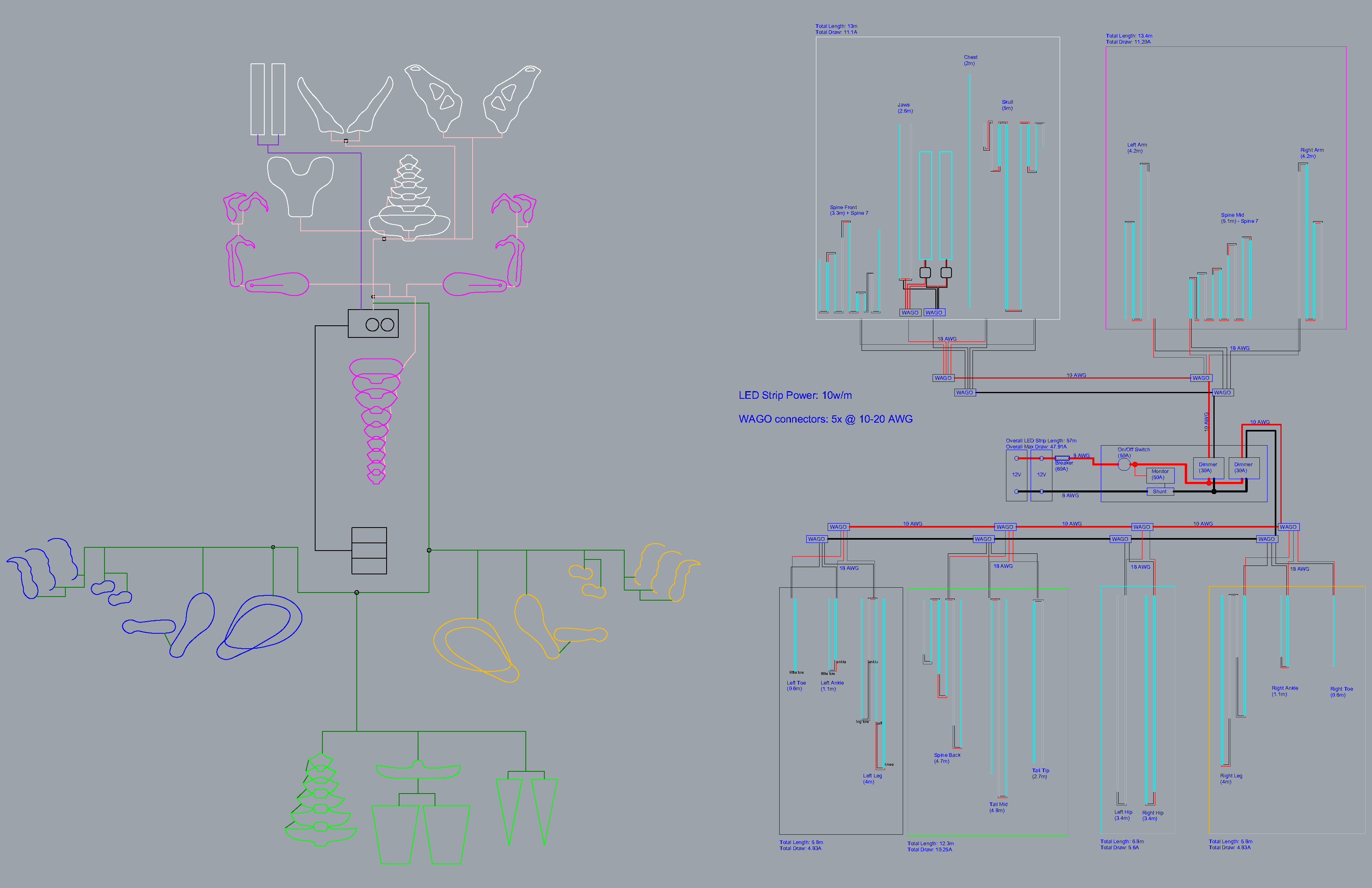
The wiring has been mercifully simple since it’s only split into two channels, and 95% of the lights are on a single channel (everything but the teeth); all I’ve really had to consider was the total length of strips connected in series, which are limited to <5m each to minimize power injection needs. On paper, the lights are 10w/m and the entire system should draw 44A max, but in practice it only draws 17A max, which I dial down to ~3A via PWM dimmers for optimal brightness (zero heat issues from lights or wires, so presuming the delta is due to collective voltage drop). All the wiring was planned for the higher amperage, so the mainline that each segment branches off of is 10awg (downsized from the original 8awg), with 18-20awg leads or connectors branching off to each strip segment via wago hubs.

Main interest in upgrading to addressable LEDs is uniform color changes. However, I’m discovering wiring a dozen channels of addressable LEDs would be far easier than wiring a dozen RGB strips, and there’s definitely a possible world where some programmed animations (and even some x,y,z pixel mapping) might be called for, hence leaning into Pixelblaze.

General plan:
Want to make sure I’m thinking through the hardware, power, and wiring aspects of this correctly.

For the lights, I’m looking at these individually addressable 12V 120 LED/m WS2811 strips, with a power draw of 14.4w/m. The 120/m density seems like the sweet spot between enough lights to look gapless inside a silicone diffusion tube (or half of one at least), without being an excessive amount of pixels to drive. Still puts me in the ~7,000 total pixel range. Also considering these 12V 96 LED/m WS2811 strips, the diffusion should still look adequate but the pixel resolution drops considerably (3 LEDs per pixel, ~2,000 total pixels) for the same 14.4w/m power draw. Does either sound inappropriate on its face, either because 7,000 total pixels is too unwieldy, or because 96 LEDs/m / 32 pixels/m is a disappointingly low density or resolution?

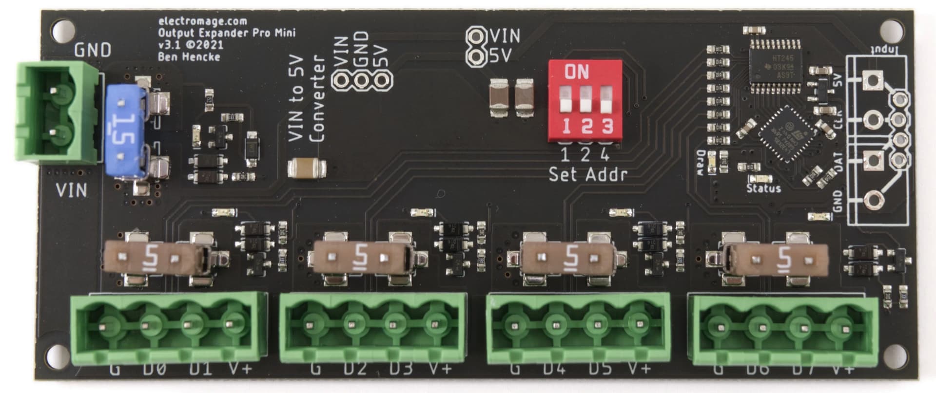
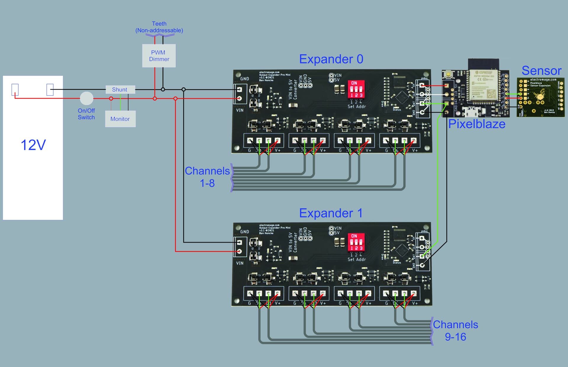
For the hardware and power, planning a Pixelblaze V3 + 1-2 expander boards + mini buck for powering the boards. I’d like to retain the current 10awg mainline for powering the strip segments, feel like it’d be a rat’s nest of wires otherwise. Are the regular expanders sufficient if I’m not powering the strips off the board (so the 15A v 3A power difference is irrelevant), or is there another reason to consider using 1-2 pro boards instead? Any additional considerations here given everything is running off 12V batteries?

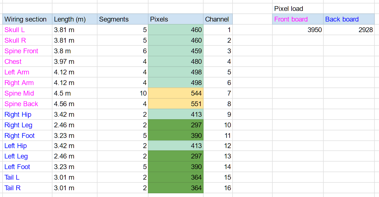
Lastly, curious where/how I’d start thinking about pixel mapping this beast. I could get pretty far doing a 2D map using a tool like this Google Sheets-based mapper with a top-down, roadkill-style layout, but there are enough overlapping pieces that thinking in 3D could really dial things up to 11. Since I don’t have much of a coding background, is there a way to, I don’t know, take a CAD model of the LED layout and covert that into a x,y,z pixel map? Or something else? I couldn’t make heads or tails of the tutorial documentation on pixel mapping, so hoping this isn’t completely outside the realm of possibility.

Feels good to get all that off my chest. Really looking for insights on the light strips and Pixelblaze hardware options, and making sure I’m not overlooking something that might cause a fire (since, you know, I’m wearing all of this). Thank you much!

3 Likes

If you want the best solution to the diffusion problem then you might want to consider these: https://www.aliexpress.com/item/1005005046710332.html The downside is that even with the 720/m strips you only get an effective resolution of 20 pixels/m. That might still be OK - in my experience you can get away with quite low density for animations (e.g. this is 30/m strips: https://youtu.be/scWQAmMJdVs). Bear in mind that your LED strips are outlines around the dinosaur with often quite large gaps between each strip, so even with high density strips you only get an effective resolution increase along the strips themselves anyway, and not across/between strips. When you have high resolution in only one dimension I find that you can end up with an appearance of everything looking like it’s animating along the strips, rather than in 3D space (if that makes sense?!). Maybe others can chime in here, as it’s obviously quite subjective, pattern dependent etc too.

Hopefully others can comment on the expander and mapping questions.

Looks like a great project, looking forward to seeing the end results!

I agree with @ChrisNZ; I’ll add that 2D animations will be perceptible and 1D animations excellent, but 3D might not read that easy on this (awesome) project.

Your understanding looks correct about the pro vs default expanders.

If I were in your shoes I’d still ask a strip manufacturer (e.g. Gree, Shiji, Normand, Ray Wu) if they can make you the density you like, like 120/m, in GS8208s. With the internal WS2811’s, you never know what you’re really getting. The PWM can be a trash 400Hz which will film horribly, you don’t get the backup data line, the quiescent current can be quite bad making for hot strips and low battery life, and the low brightness color response is horrible and steppy for gradients and animations. By having a custom strip made, you could also ask them to fill it with a diffusive milky silicone (“IP68”) which should be good for durability and diffusion.

While I’ve wired up the higher density COBs like ChrisNZ mentions, and they do look beautifully diffuse, I do worry about their durability a bit (but I don’t have much direct data on this).

No matter what you pick, it’s worth calculating your longest run and testing that on an output expander, looking for flicker. Under 250 you should be fine, up to 500 can also be quite reliable, but over 500 per channel is a situation I always want to test for a variety of signal and power issues.

There are some examples here in the forums where people have exported from CAD to generate a map; that seems to be a good solution. You should still generate it in 3D so you can easily code some 2.5D patterns that target certain layers, and make sure your primary view (side view) is exported as an X-Y plane (constant Z) so it’s really easy to adapt any 2D patterns you like.

Was this page the mapping tutorial that was confusing? If so, I’d like to make it better (you’re not alone in having this experience) but I’ve had a hard time getting specific feedback on where I lost people.

I have a lot of experience working in 10AWG and Wagos, super fun :wink: If you’re not already, I highly recommend using the 221-61X series over the common 221-41X ones if you’re branching 10AWG.

Thank you both!

@ChrisNZ, appreciate the link, and agree 720/m would “address” the diffusion issue right out of the box (the current strips are 720/m, and they look beautiful). The challenge here is PCB width and horizontal bends. Current strips are 5mm and threaded through heat shrink tubing, which is then affixed to the EVA foam body with contact cement. Some places have perpendicular corners I need to navigate around, and the smaller PCB lets me get away with rolling it up from the edge onto the front as needed. The chest is a good example, here’s a close up:

Those sort of moves get messy with any PCB flapping out beyond the lights themselves. For the new addressable setup, I’m ditching the heat shrink, cutting the 360-degree diffusion tubes linked above in half, and affixing them to the edges of the foam (how I’m going to adhere silicone to EVA foam is a whole other question, that’s my next experiment before really committing to this). The thinking is I can run the new strips down the edges, twist them where necessary (instead of rolling them onto a different surface), and affix the diffusion tube on top of them. Cutting a tube in half leaves some vertical space for the twisted strips where needed with additional flex from the foam, which would not be available with an enclosed 180-degree half dome (also no need to pull strips through any fussy tubing, which is a huge time saver), and since they’re 360-degree diffusion tubes, it shouldn’t matter which way the strips are facing so long as they aren’t facing straight down. That’s the thought at least.

All that said, I started the addressable LED search with the 5mm restriction, tried out some 5mm 5V 160/m strips, was underwhelmed, and kind of shocked to realize 5V strips consume more power for less punch compared to 12V strips, so here we are. I’m even fretting over the 6.5mm PCB of the 96/m strip compared to the 5mm PCB of the 120/m, so on all counts, I’m thinking the 120/m are the way to go (grumbling about the additional cost, but so it goes).

@jeff, thanks for confirming the pro vs default expander logic, and providing the additional channel math considerations. Longest single run is the chestpiece at 6.5ft, so only ~300 pixels @ 120/m. With two expanders, should be able to fit 7,000 pixels across 16 channels or less and still keep each under 500 pixels, so that sounds like a win.

Had no idea I could just ask a manufacturer to fab something custom for me! Have you ever heard of GS8208s being mashed into a 5mm wide form factor? Would imagine the cost would be substantial, unless this is a fairly common exercise?

Agree with both of you 3D patterns would not translate especially well. The most complex 3D patterns I’m imagining right now are full color wipes from head to tail, and wondering how I’d translate the chestpiece (which is mostly vertical and front-facing) and the toes (which are stacked) into a 2D map for something like that. Probably just need to play with it; would love to hear more about coding 2.5D patterns, that sounds like the real solution here.

Also happy to provide feedback on the tutorial page, thanks for soliciting it! What’s the best way to provide it, DM? Email? Start a new forum thread?

And lastly, confirmed, using 221-615s, paid very close attention to component power ratings top to bottom :wink: Wagos are such a game changer!

1 Like

First off – I LOVE this project – I’m pretty sure I’ve seen it and talked to you about it at a small private event in Lake County California last year, and if you’re going to be there again in two weeks, look for me if you want to chat! I’ll be wearing a 2D mapped wearable LED cone hat at night that will be… very distinctive.

While you’re discussion with Jeff about the smaller output expander boards working fine is, of course, correct, I’d consider your overall wiring plan here. Because you have the space, and because you’re dealing with a bunch of power runs anyhow, I would personally use the 12v Pro Expander Boards for BOTH power AND data. My reasoning: It takes one item of complexity out of your system – you don’t need to run power and data separately / across different systems, it comes with the built-in fuses, handles the 12v for you so you don’t need to use mini-bucks, lets you use screw-terminals on the Pro Expander Boards instead of a lot of soldering and extra Wagos, etc.

The quality of life enhancements would steer me in that direction for sure – what’s the “rat’s nest of wiring” issues you’re worried about – keeping in mind that you’re going to be re-wiring the whole thing anyhow to switch LEDs.

My other thought: you don’t need to be driving the LEDs that bright or that “white” – you’re going to be pulling a lot less power than you think, unless you’ve already measured otherwise and I’m missing something. Check Overview | Sipping Power With NeoPixels | Adafruit Learning System for an overview of why / some basic assumptions you can make. (The article is written for old-school controller hardware, but everything in it applies here).

For similar reasons, I’m curious why you need 10 gauge wire here – at least after the main connection between the power supply and the Pro Expander boards. @jeff has worked on some massive art cars and the like where the power management is bigger and way more power draw, and sure, it makes sense there – but given YOUR specs (and the fact that you’re carrying the batteries and the whole system around) I’d check some online calculators and consider going to something more like 14 gauge myself.

3 Likes

Ah, I didn’t understand you need (or want) to stay with a thin strip, like 5mm wide. Unfortunately they don’t make GS8208s in a size that will fit on a 5mm wide strip yet (like 3535 or 2020 chips). I think you’ll be stuck with WS2811 in 12V, and it would be a lot of buck converter wiring and power injection to get to something more beautiful (like SK9822-2020) in a 5mm strip.

I agree with @ZacharyRD that lower brightness is probably fine. Pro Expanders are a nice convenience if in your budget, and I’ve been where you are where it’s like, “well, I don’t need the 10AWG but it’s all stripped to the right lengths already!”

The fun of mapping is that you can try a few after it’s all wired up and see what looks best.

A 2.5D approach would be to map each layer as XY, then use a different Z for all of the LEDs in a particular plane. So one constant Z-coordinate for each side of the spine, one for each leg, one for each toe, etc. It’s creating a bunch of flat layers in space. It may or may not look great for the chest. If mapped from the perspective of someone looking at the Dino’s right side, a pattern that flowed from +X to -X would flow from nose to tail.

Another approach is to imagine the entire surface is made out of a single sheet of paper, and that you unfold that paper somehow into a single 2D XY plane. This could look good for both the sides and the chest. If a pattern has a 3D renderer, you’d just use the 2D version and it would probably still look good. If you unwrap it how I would, a pattern from center to the edges would flow from tip to tail. This might be similar to what you were saying about a “roadkill” layout.

Good luck, can’t wait to see how it ends up!

1 Like

You mean the tupperware party in the woods? That was indeed me, sans LEDs :joy:. Will not be there this year, but just had an amazing run at Bay to Breakers, will be happily wandering around SF on agreeable evenings all summer, and will see you at the big burn!

Would LOVE to geek out on the wiring, please convince me there’s a better way. Frankly I love the convenience of the built-in 12v-5v buck and the regulated power in the Pro, feels safer and more durable all around; just thinking about price and layout.

Here’s what I’m currently working with (slightly modified from these initial drawings, but same basic idea):

Batteries sit in the back with about 5’ of mains running to a control box. Box has two dimmers in it, which now run to the teeth and to everything else (per the drawing on the left). For the body, it’s just the one mainline out to a series of 5-channel wago splitters, one for each region on the body (front, to torso, to right leg, to tail, to left leg). The mainline lets me keep the lead wires for each section relatively local, with minimal wires running from the control box up and down the length of the frame. The “rat’s nest” feared would be (let’s say 16 channels, 3 wires each, so) 48 wires spilling out of the control box routed in all different directions up and down the frame, which feels cumbersome and unmanageable. @jeff nailed it with “I don’t need the 10AWG but it’s all stripped to the to right lengths already” lol. Was working off the assumption that a PWM-dimmed LED still pulls it’s maximum power, but is blinking so fast it appears dimmer on average, so the wiring should still account for the maximum power draw even when dimmed by default.

That said, suppose I could find a home for the second expansion board somewhere in the back near the battery, so I have a front hub for the teeth/front/torso, a rear hub for the legs and tail, and only a single 3x wire running between them. Could also run some 18/3 wire instead of the flat ribbon-style connectors to keep things tidy, and if each channel is 500 pixels or less, that’s less than 5m per channel at 120/m, so… might not even need any power injection cables. Curious. Your thoughts?

Also, couple rookie questions about the Pro expander board:

I see the 4 outputs are each [V-, D1, D2, and V+]. I assume that means V- and V+ are shared between two channels (so 2 black wires in V-, channel 1 green in D1, channel 2 green in D2, and two red wires in V+)?

Also, how exactly would I wire the two boards and the Pixelblaze together? 12V in via the top left port, then both the Pixelblaze and the second expander board via the inputs in the top right (either directly or with header pins), with each board set to the appropriate address?

Thanks Jeff, this is super helpful. Already loving this community, you guys are great!

Agree that thinner PCBs are limiting. How do other people deal with horizontal bends? Is it possible/common to maybe splice in some zigzag LEDs at those points, and do the LEDs/chipsets have to match if so?

2.5 mapping sounds spot on, that’s exactly the solution. I’ll have to just get my hands dirty and start messing around with it, but knowing I can break the design up into stacked layers is huge, and all I really need here. Much appreciated!

That’s a good idea; the chipsets would need to speak the same protocol and color order within that protocol but I bet that’s workable.

I haven’t done a ton of projects that need to bend in the awkward direction of a strip, but when I have, I’ve typically folded the strip on itself. You’ll sometimes be left with a misplaced pixel or two. You can disable it in your patterns if it looks too bad.

Another approach I see a lot is to solder 3-4 short insulated wires to make whatever custom bend. Looks like a lot of work.

It can be pretty convenient when you start your project with a particular LED form factor in mind, then design the shape around its limitations.

1 Like

With 12v, your need a LOT less power injection than 5v, just in general – and I’m pretty confident you can build this to not need to do so, especially as you pull down the maximum brightness.

You nailed it – there’s shared power across two data channels is the easiest way to use that board. (which is 12v / 5a across the two data channels – it’s plenty of power for what you’re doing, I think).

I think – although @jeff can confirm – that to run two expansion boards in series, you use a PixelBlaze as the input on the first expansion board, and then use D0 of the first board to be the input of a second one.

Close - you just parallel the Pixelblaze ground and data output line to all expanders, creating a bus. Each expander only listens to the part of the output signal intended for its particular channels.

1 Like

Is there a 5V out I can pull from the first expander to jump to the second, or would it be 12Vin via the top-left pins on both boards, Pixelblaze connected to the first board, and the ground/data lines connecting the Pixelblaze and the first board also connecting the second board?

I’ll draw all this out to confirm, but think Zach convinced me Pro boards are the better way.

2 Likes

The input voltage to the pro expanders will need to match the LEDs, so 12V.

The Pixelblaze will still run off the single minibuck to get its 5V.

2 Likes

Got it. Alright, next steps for me are to draw out the Pixelblaze setup, plot out the LED channel distribution and length, and draw the new wiring diagram. Appreciate your comments on overlapping LED strips as well, in hindsight this was not an option with the COBs due to their density, but now it seems like a viable solution.

Thanks all, stay tuned!

Ok, so think I have everything squared away. Is this accurate wiring for the Pixelblaze side of things?

Rookie question, but no issues with having the PWM power siphoned off the battery prior to hitting the expander, correct? I’ve had issues with flicker before when dealing with multiple controllers, but changing up the resistance at the PWM has generally resolved it. I’m guessing the board regulates power enough to handle VIN noise without any problems or additional resistors in the line?

Distribution worked out pretty well, front board has more load than the back, mostly kept channels under 500 pixels, feel this is all comfortably within spec. “Segments” refers to the number of pieces connected in serial (e.g. the 10 segments of the “Spine Mid” channel are individual vertebrae). Might need a couple power injections for the spine, but happy everything is under 5m.

Confirming that 18-gauge (18/3 stranded) wire is the right call here, with 18-gauge JST connectors to match?

What an amazing puppet!
The 8 year-old in me is awestruck, and now you are upgrading to addressable RGB LEDs, that’s a dino and a GOAT!!
It looks like your dinosaur is about 9 feet tall when you stand upright?!
And when this upgrade is finished you know you have to post video!! :wink:

Thanks! :dancer::t_rex::man_dancing: Went viral on Tiktok a couple weeks ago, here are a couple favorites (have to rely on other people posting videos to the socials because, you know, I’m busy piloting the thing). Very excited to post videos of the upgraded LEDs once they’re on and mapped!

Early evening stroll at the park, and night strolls around the Mission.

1 Like

I think the PWM dimmer won’t pose too much of an issue, but only a scope will tell. The Expanders do not provide much in the way of power conditioning. Big capacitors across the rails can be a help as well, generally even more than an inline resistor on the data outputs (which is already in Pixelblaze and the expanders).

18 AWG should be good for handling up to 18 amps (~1500 12V 5050 LEDs, but you’ll need to measure your own strips); Voltage drop dimming and red-shifting the LEDs will generally bight you before the max current rating of the wire, so unfortunately it’s another one of those “gotta test your setup” things.

Thanks for the links! You must have an absolute blast when you head out for a stroll in the evening. You are a gifted entertainer and a builder of things.
I was going to ask if you had any audio, roaring, etc., but now I’m thinking a little Disco?!
btw I can attest to @jeff’s recommending the use of capacitors on certain parts of a layout. In my experience, once you figure out the values (trial and error for me), they can really absorb spikes and delay dimming on the farther reaches of a project. The right capacity can pretty much eliminate flicker.
Not gonna say, “Have fun!”, because I know you are!

Oh yeah, have audio on lock. Speaker in the mouth, two paired big ones in the back, all bluetoothed to two old phones I have on the steer running soundboard apps. Roars, talks, meows, burps, farts, does a lovely pantomime to holy fucking shit it’s a dinosaur, and plays a delightful assortment of house and disco tunes. He’s a crowdpleaser :wink:

2 Likes