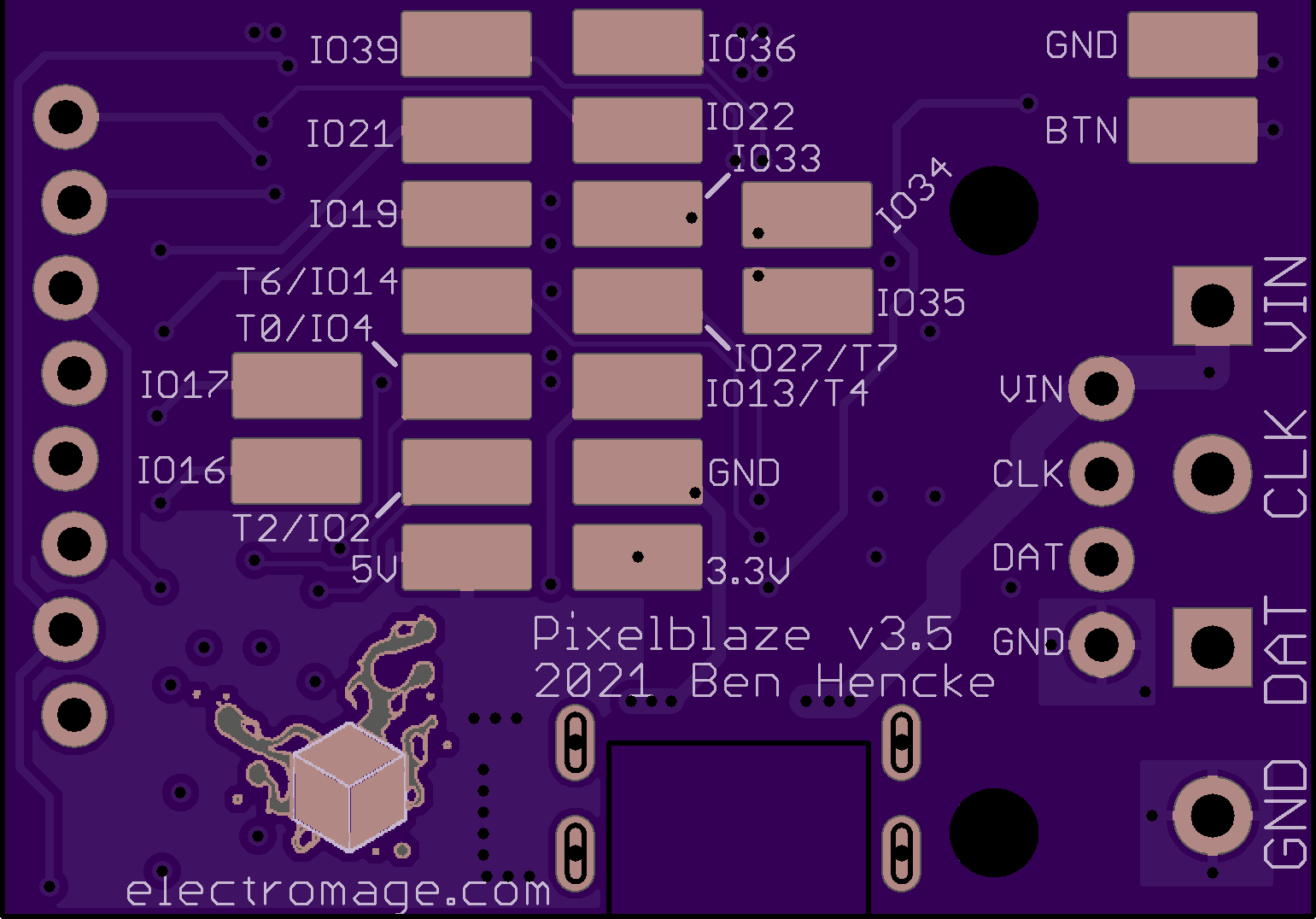
I’m working on a revision to V3. This breaks out a bunch more of the GPIO, and should give us access to more analog inputs, which was unfortunately limited in initial V3 hardware.
Here’s a preview of the underside using OSH Park’s awesome render for a strict superset:
Looks a bit cramped, yeah? As I cram more and more into this form-factor, I keep wondering if a new design that’s a bit larger would be better than keeping the original form-factor. Perhaps an XL model or something? What about a double column for the expansion header, or would a spaced pair work better for direct board mounting?
What would you like to see in a new form factor? Is keeping compatibility with the existing form factor important to you?
So if the original sensor board needs to fit, that limits the first row of pins. Maybe a second row of pins with the additional lines? Then potentially adding a new board makes sense?
The problem with the pads underneath is that you’re basically limited to a solder pad connection. The Pico suffers from this, too, since there is no clean (ie nonsolder pad) way to add a sensor board. (If there were pinholes, then adding a sensor board to the Pico would be trivial, just a few jumper wires, no pad solder worries)
Is Anyone using (and needing) those solder pads that wouldn’t be better served by a row of pins/holes?
I can imagine it may be difficult to replace the pads in the central area with holes, since they would be under the module on the other side of the board. Personally, I’d have no issue with a slightly larger form-factor if that made it easier to add stuff. If the size was to change, I would welcome slightly larger mounting holes, perhaps to take M3 screws.
Another feature that I would quite like to see would be support in software / hardware for a few more buttons (either discrete inputs, or sensed via a single ADC line with each button grounding part of a chain of resistors), or even support for a couple of rotary encoders. But maybe I am getting carried away…
I think not, I don’t imagine anyone would find the pads optimal other than for space saving reasons. But it would impact the size and form-factor, which could impact folks. This really is legacy at this point, the form factor came from the original Pixelblaze which didn’t have any pads or pins broken out aside from the outputs and expansion header. V2 added some pads because that was the only place it could. V3 and V2+ grew a little to accommodate the larger ESP32 module and a button, with the V3 getting heaps more pads which I think are infrequently used - but I don’t want to assume too much, so if anyone reading this has opinions, please toss in your 2 cents!
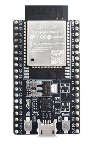
Would something breadboard friendly be important? I never thought so for LED-only projects, but for hybrid LED + embedded where you add sensors and things, prototyping on a breadboard is handy. Thats the direction most dev boards take, but it adds to the size quite a bit to break out everything on a pair of 0.1" headers, and with the esp32 module itself being quite wide you end up with something like this:
Perhaps this is fine for an XL variant, and I should additionally keep the smallish form factor, or something close. Maybe a double row header along the expansion port side.
I think I’ve used 20-25 Pixelblaze, and replacing one in-place from V2->V3 never happened, but I did use the sensor board pinout compatibility often, and continue to appreciate the stacking options.
I’ve never minded the solder pads. Most of my projects don’t use them. When I have, they seem easy to solder to. I use the IO pins on the header more often.
In one project I did miss the third mounting hole v2 had, once. It felt more secure against bumping. Rare though.
Hardware wise, I think I’d most enjoy in an XL:
12V feedback capable (onboard buck?), like the Pro Expander. WS2815s have become popular.
Pluggable screw terminals by default. I’m always soldering up an array of JST-SM 3 and 4 position “adapters” to swap something, ground my backup data, or make 3-position strips just adapt to the 4-position JST I like to leave on all my Pixelblazes. I don’t love re-screwing because I’m afraid I’ll short something.
Is there already a PTC or other over-current protection for Board → Strip power?
External WiFi antenna plug
Onboard status RGB LED that I can send data to, IE blink or color myself
I can say with confidence though, that if there were some clever enclosure kits sold on Tindie, I would probably purchase them with my PBs frequently. Clever would be like:
Accepts a sticky label easily, or smooth wet-erase surface on top
Opposite corner tabs with holes for screw/nail/hang mounting
PB snaps in on mounting posts, and is removable with moderate force
Thin knockouts to reveal USB or header via X-Acto
Accepts sensor board default stack above
Extends button to enclosure surface
Translucent for status LED, or small hole
Tested for WiFi effects (I can accept degradation, just want it known before)
Some clever option for DIY ingress protection. For example, on Picos I like the clear heat-shrink sleeve with a shot of silicone or hot glue at the entrance around the wires (and heat-seal the far side).
@Scruffynerf I agree that getting sensor board data to the Pico is not as convenient, but what’s the use case where you really need the Pico’s tiny-ness, but also have space for a sensor board?
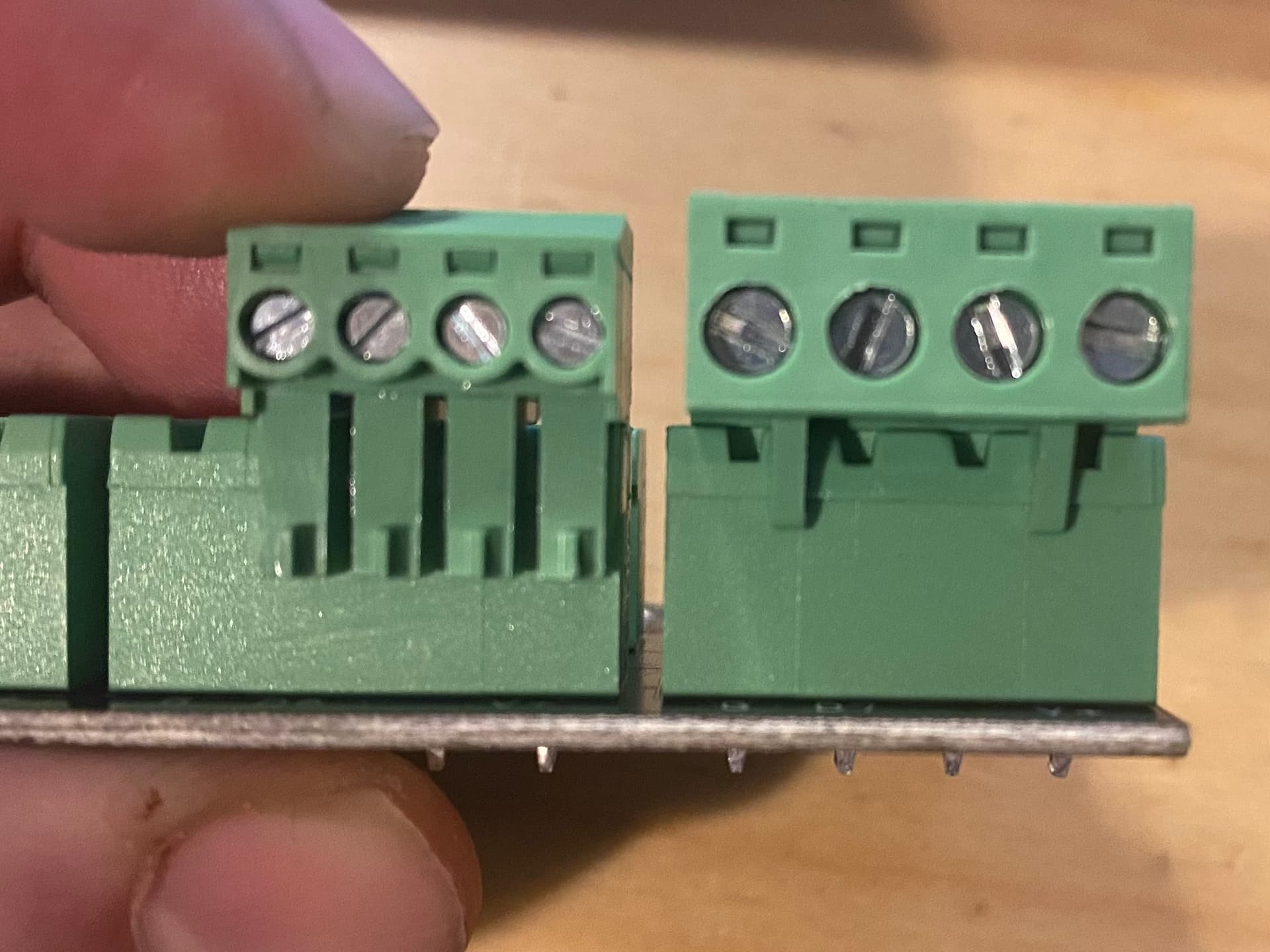
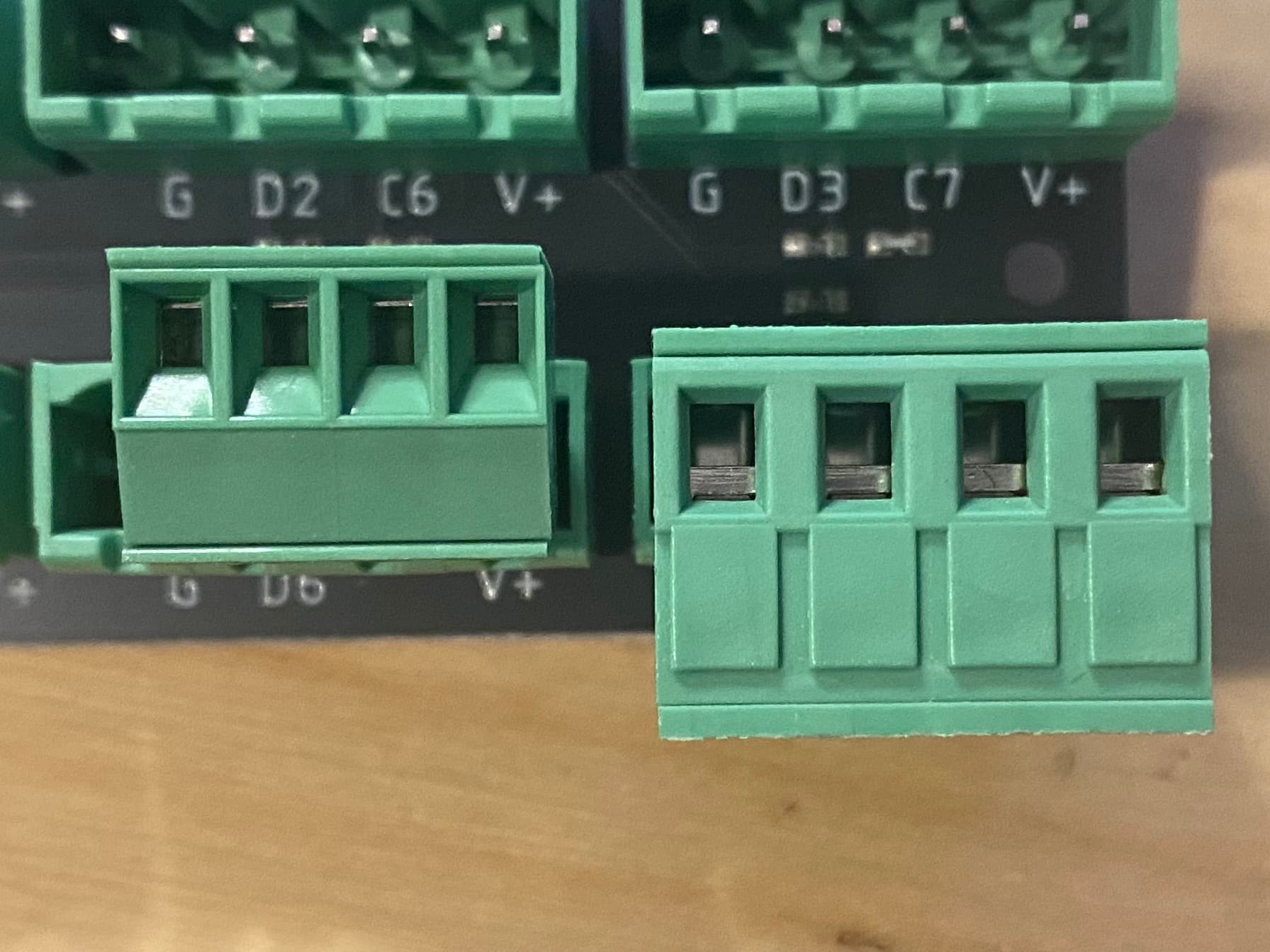
Would the same pluggable terminals I use on the Pro boards work? These fit, they are just comically large for the small V3 standard board. There’s no reason I can’t offer this as an option.
I like everything about that theoretical enclosure. I’m totally stealing this as my wishlist / design requirements.
The only ‘big’ thing about the sensor board is the jack. A jackless sensor is quite small. I want to build a few hulahoops/poi, and a full size PB is too big, but a sensorless unit feels too limited, I really want the sensors.
I wonder if someone has tried it with the larger version. The thing with a mic based approach is that I could see it picking up a lot of white noise as air blows past the mic.
What about an even smaller version, no sensors at all? Sensorboard sharing is on my near term list. You could run a full PB + SB off to the side, even aux jack for super clean audio, and the picos in the hoops/poi would get a clean SB data over wifi.
Possibly dumb question: what is the advantage of using the larger ESP32 module in the standard PB, vs the smaller “bare” chip that’s used in the Pico? Could elimination of the full module free up some space for fine-pitch connectors on the edge of the PCB (e.g. JST SH 1.0mm series) to bring out more i/o?
There are a few advantages. It’s FCC / CE certified, slightly better antenna performance, has options with more flash (for future versions), better heat distribution, and is slightly easier to manufacture with.
I’ll still be making the Pico dev board, but it wouldn’t be as easily sold as or integrated into a consumer product as something based on the module would be just from a regulatory certification standpoint.
The fine pitch stuff is harder for folks to solder, and I want to keep things pretty accessible for the Standard line. I could totally see using a small board to board connector for expansions, though the minimum 6 pin header isn’t that large with the Pico’s small form factor being a notable exception!
If you did 12 pins (or even up to 16 pins?) in 2 rows, that seems pretty add-on friendly, and depending on how it’s soldered (ie it could be pins down into a connector on a board, that seems pretty stable.)
have you considered adopting the feather form factor? that would potentially open up use of PB with a whole ecosystem out there? the sensor board could be another feather board
then the pico could continue to carry the banner for when space is an premium.
This++ … but I’ll say that my solution was to permanently screw in a 4-wire connector (so permanently that I might just remove the screw terminal and solder in the connector) … and then I have a bunch of very short cables with the 4-wire connector on one end and whatever else (e.g. 3 wire, with data going nowhere) on the other. Because these strips from AliExpress are randomly soldered, I have a few same-gendered adapter cables and a few cross-wired one.