Does anyone know what’s happening here? Hsv(1,0,1) is showing as white in my strips but blueish green in my fibonacci panels.

Different LED types is my guess. What were the strips?
These are the strips I bought:
WS2812C-2020
Not sure what LEDs are used in the panels, @JasonCoon would know.
They “look” the same to me haha
is there a way to set color correction/white temperature correction? I guess I would have to set the value differently for each segment. I never notice it on rainbow patterns just white so this may not be worth investigating.
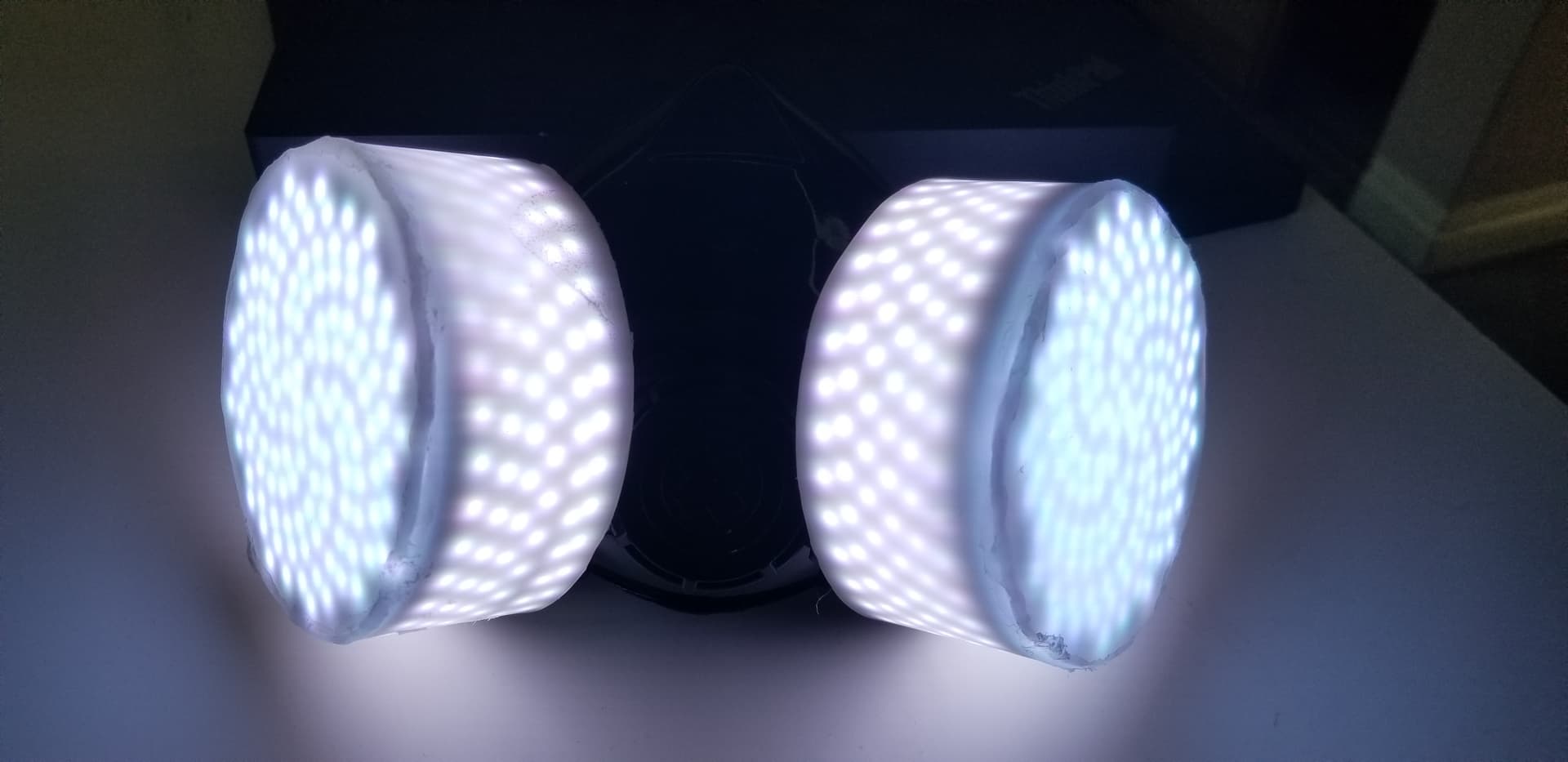
on white at 20% brightness the LEDs were so hot I worried they would melt the plastic diffusion covers (they’re heat mold plastic)
Also the PixelBlaze is glued directly to the Lipo and that was getting really hot too.
I think I should insulate the PB from the battery and retest. I’ll need to limit the brightness/power draw.
More importantly, I would love a way to lock certain settings from the UI.
I don’t want some less tech savvy customer changing the Limit Brightness setting from 20 to 100 and literally melting their face off. This reminds me I should really add a fuse on the power line.
The 75mm F128 PCBs have WS2812B-2020 on them, which I guess might explain the color difference. I know FastLED allows you to set the color temperature and/or correction separately for different sets of LEDs, but I’m not sure about Pixelblaze.
The next batch I order I’ll use WS2812C-2020. Honestly I thought I ordered those for this set, sorry.
WS2812C-2020 are 5mA per channel, so 15mA per LED.
WS2812B-2020 are 12mA per channel, 36mA per LED, 4.6A total for F128, when running solid white, max brightness. Heat would definitely be a problem under those conditions. I limit max brightness in my firmware using FastLED to 50% or less, and limit max current well below that.
yeah heat is definitely an issue. I was just using hot glue melt to glue the panels and strips to the mask, but on white all the glue melted and panels just fell off. Might look at using E6000 once I have everything else finalized (I’ve been glad these are removable while I make alterations to the internals of the prototype).
WS2812C would be much better from what I read from World Semi
WS2812C LED is similar to WS2812B LED, the only difference is lower current,we have changed the current from
18.5mA to 5mA.
With lower current, the brightness reduced to one-third of the original, so do the power consumption reduced
I definitely prefer lower current and lower brightness for these purposes.
Yeah, totally agree, I’ll ensure all my future boards use C instead of B.
If the mask is hot enough to melt hot glue, that might also be hot enough to reduce the life of the LEDs.
Is there any way to channel the wearer’s breathing through slits in the mask “cartridges”, to provide a little active ventilation?
1 Like
| that might also be hot enough to reduce the life of the LEDs
this was a concern as well (albeit less of a concern than a battery fire).
I started this as a battery runtime test, but I’ve aborted the test until I can resolve some of these other safety concerns.
The valves in the mask pull air from the cans and push out through a small exhaust port in the bottom center of the mask. I left the valves in mainly to prevent any breath moisture from getting into the electronics. it’s not much ventilation, and I don’t want users always breathing in hot air from the PB/Battery/LEDs. I would rather focus on limiting heat entirely.
You can enable “simple UI mode” by adding “?setup” to the url and going to the advanced tab. Simple UI mode removes all the dangerous stuff and you can lock down a brightness limit % via settings.
You could add some rgb/hsv wrappers that check pixel index and do different things for the panels and strips, such as some color tweaking for whites and additional brightness adjustment.
This is all wired up as 1 long string, right?
Addressable LED chipsets/implementations can change the color balance, but the LED dies themselves can vary. Mostly it comes down to a few factors such as current response and exact LED chemistry, including process variations during manufacturing. Not all LEDs end up exactly they same, and they sort them into “bins” of similar LEDs. Manufacturers of addressable LEDs might take these and allow customers to likewise get similarly binned LEDs, but in my experience this is not super common or well supported.
WS might have better quality control than most, but even if they used the same binned LED die in both the 5ma and 12ma versions the different drive current will change the balance. They would have had to balance them out taking all those factors into account - maybe even needing to add laser trimming to the current drivers for each channel for each chip, which could get expensive I imagine.
BTW this would be an excellent application for HDR LEDs like the apa102/SK9822 and newer 16-bits per channel chipsets like the HD108 and WS2816. You can go to much lower brightness levels and still get excellent mixing capability, and I’m working on adding support in PB!
3 Likes
Simple UI mode is perfect
yeah it’s all wired as 1 long strip.
It sounds like this may be resolved by getting the panels made in WS2812-C
Given the heat concerns with the current model, I’m just going to delete the all white pattern or reduce the hsv(1,0,1) to hsv(1,0,0.2) or something so low it doesn’t get hot.
Can anyone recommend a good small inline fuse for this? I have some mini-blade 4Amp fuses, but the inline cases for those are a bit too bulky. With the PB standard, sensor board, lipo, and adafruit lipo charging backpack it’s getting a bit cramped inside the first can.
1 Like
@wizard’s got a tiny lipo charger in his store now
We just need a combo Pico/sensor board now… And then you’d have plenty of room.
2 Likes
I didn’t realize @wizard’s lipo charger had a 4A protection. The adafruit backpack does not that I saw. The only thing I like about the adafruit backpack is the red led for charging and green led for done. I didn’t see that on the one you linked so how do you know when it’s done charging?
Also the 212ma charge rate is a bit low for my 2ah batteries, that would take 10 hours. the adafruit backpack does 500ma charging so 4 hours on my batteries. probably not a big deal, I assume most people just leave it charging overnight (I know never charge unattended, but it happens).
LilLiPo might be a bit too little for your 2AH batteries.
It doesn’t have a charging LED. For what I use em for its either a fast charge for really tiny batteries where the charge current is about 1C, so an hour or so, or for larger setups I tend to leave em overnight. The IC I used could do 500mA, but the PCB isn’t designed for the thermal ramifications and would likely go into thermal throttling. The adafruit board uses the same style linear charger and would have the same heat generation, but probably has more copper spreading it around so the IC can keep going. I bet it gets hot to touch even so!
It seems like a waste, but you could use both where LilLiPo is just for battery protection (short protection and under voltage) and you charge via the Adafruit board. Similar protection ICs can be found in small lipo packs (it depends, many dont, some do), but rarely integrated into 18650 style cylinder cells.
Also the HD108’s use less power when turned “off”. Supposed to be like 90% less… so if you are using patterns that have some off pixels that could also help reduce heat.
FYI: good explanation of how those lipo chargers work:

What if anything would anyone recommend for heat insulation between the PixelBlaze V3 (which to me gets a lot hotter than the V2 right?) and the lipo battery I’m using (in this case I switched from the 18650 cylinder to a flat lipo so I could fit the audio sensor).
I have some double sided gaffers foam tape (https://www.amazon.com/gp/product/B01LXJGLMC/), or some heat resistant double sided acrylic tape (https://www.amazon.com/gp/product/B0796Q7N4F/).
I was also considering buying a silicone mat and cutting up some squares, but my understanding is it’s only heat resistant in short term, then it eventually heats up and can actually continue to emit heat after power is turned off. maybe that’s true for all of these, idk. Any tips appreciated.
@Sunandmooncouture,
You are using a Standard, right? They do get a little warm, warmer than V2, but shouldn’t be getting hot in open air as the PCB and metal shield help spread the heat over a larger area.
The heat has to go somewhere, otherwise with perfect insulation and infinite power and time it would eventually turn into a small star. Rather than insulate it, which traps in heat, can you move the heat to a location that can breathe?
I’d get a cheap IR thermometer and take some readings. If you aren’t getting over 100F I wouldn’t worry about it as it won’t harm the lipo. If it is, I’d worry about why its getting that hot in the first place!
1 Like
@JasonCoon so WS2812-C is perfect for now, but what would it take to make these panels in HDR chipsets? Do they even sell 4mm strips in HDR? I’m not even sure I can see the difference, need to build a side-by-side test harness. Maybe time to buy one of each of @wizard’s matrices for testing. or does anyone have a video of side by side comparison? Can you even tell the difference in videos or just in person?
1 Like
You might also want to see if an extra heatsink will help reduce where it’s getting hot (heat moving toward the heatsink as an easier path)
Generally the advice around lipos seems to be to keep them under 115F. Higher temps can damage them - reduce battery life and can cause them to puff up. For skin contact, “painfully hot” generally starts around 111F.
For what it’s worth, I have 2 Standards on my desk at the moment and one measures 100F and the other 105F. The first feels just slightly over body temp, and the other feels slightly warm.