I’m trying to wire up a button without really grasping exactly how it all works, so even though I have two options, it’s very likely that neither will work, and in that case any help pointing me in the right direction is appreciated.
I want the LED on the button to be off, and turn on while the button is pushed. I want the PB to do something once each time the button is pushed. Do I need to connect the LED- to ground? Or can the input pin on the pixelblaze act as a ground, and then see that the button is pushed when the voltage drops?
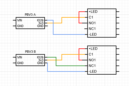
This is my attempt at a diagram to explain what I mean:
The one labelled PBV3 A is the “no ground” one that I’m asking about. But I also don’t really know if the “B” version will work. Or, if it will technically “work” whether it is the correct way to wire the LED on a momentary switch.
Version A will not work for a couple of reasons. First, IO26 will not act as a ground to light the LED, and second, the voltage drop through the LED may not result in a high enough voltage delivered at IO26 to trigger it.
But I think version B will work perfectly if you configure IO26 pin mode as INPUT_PULLDOWN, and it will read LOW when the button is pushed. Or preferably, you could connect IO26 to NO1 (with LED+), giving the LED and IO26 a more definite physical relationship, and in this case IO26 will read HIGH when the button is pushed.
Also, I’m assuming your LED pushbutton has an internal current limiting resistor? Many of them don’t, in which case you’ll need to add one.
Thank you. It seemed like it would probably not work, but I was hoping to decrease the number of wires that would have going to the pixelBlaze.
If I wanted to run 5v to the LED instead of 3 (it’s 3-6v with a built in resistor and testing at 3v it is very dim), could I still use the NO1 output to IO26 if I had a resistor between NO1 and IO26?
First - you absolutely need a current limiting resistor for the LED (serially connected with LED).
Second - 5V is NO GO! PixelBlaze IOs is ONLY 3.3V.
You can try to use resistive divider but generally this is very bad idea for the Digital IOs.
I just spent so much effort troubleshooting why I couldn’t get this to work. The pixelblaze was never reading any change to the input pin. I soldered onto the pads on the back, and the wires ended up covering the labels. 2 hours later I finally look at another pixelblaze and notice that the top input on the side of the pads with 3v3 is IO22… not 26.
So, thank you for helping me get this working without anything exploding or frying. I am glad my pile of pixelblazes I’ve ruined will stay the same size today.
Please keep in mind, the internal pull-up/pull-down resistors are
very weak (50-100K). Depend on wiring (how long is wires and
what is on the adjacent wires) input may pickup noise easily.
Recommended external pull-up/pull-down resistors are 1-5K.
Also Button better to be denounced either by SW or HW.
Sure it will work. But “small” capacitor" value depend on REAL pull-up/pull down resistor’s value.
Something like 1uF should be OK.
I was lazy to check what “Button w-debounce.epe” code is doing but small debouncing
counter in the “beforeRendser”: function definitely will do the job.
My vote is: Button debouncing is easier to implement in SW.
EMI concern is kind of irrelevant.