Wiring V2 with output expander to WS2812B strips

Hello,

I have no experience besides some soldering here and there so I’m hoping someone can give some advice. I have the V2 with an output expander, and I’m trying to feed 2 seperate LED WS2812B strips (2.8 metres long each, 120Watts each).
The power supply is 5VDC60A. I was planning on using AWG12 for power cables to LED stips, and AWG22 for data.

I don’t know whether to tie the second led strip into the first one?!

I have attached a picture with a mock up of what I think is the correct wiring, some confirmation or advice would be greatly appreciated.

Thank you!

Hi Oran,
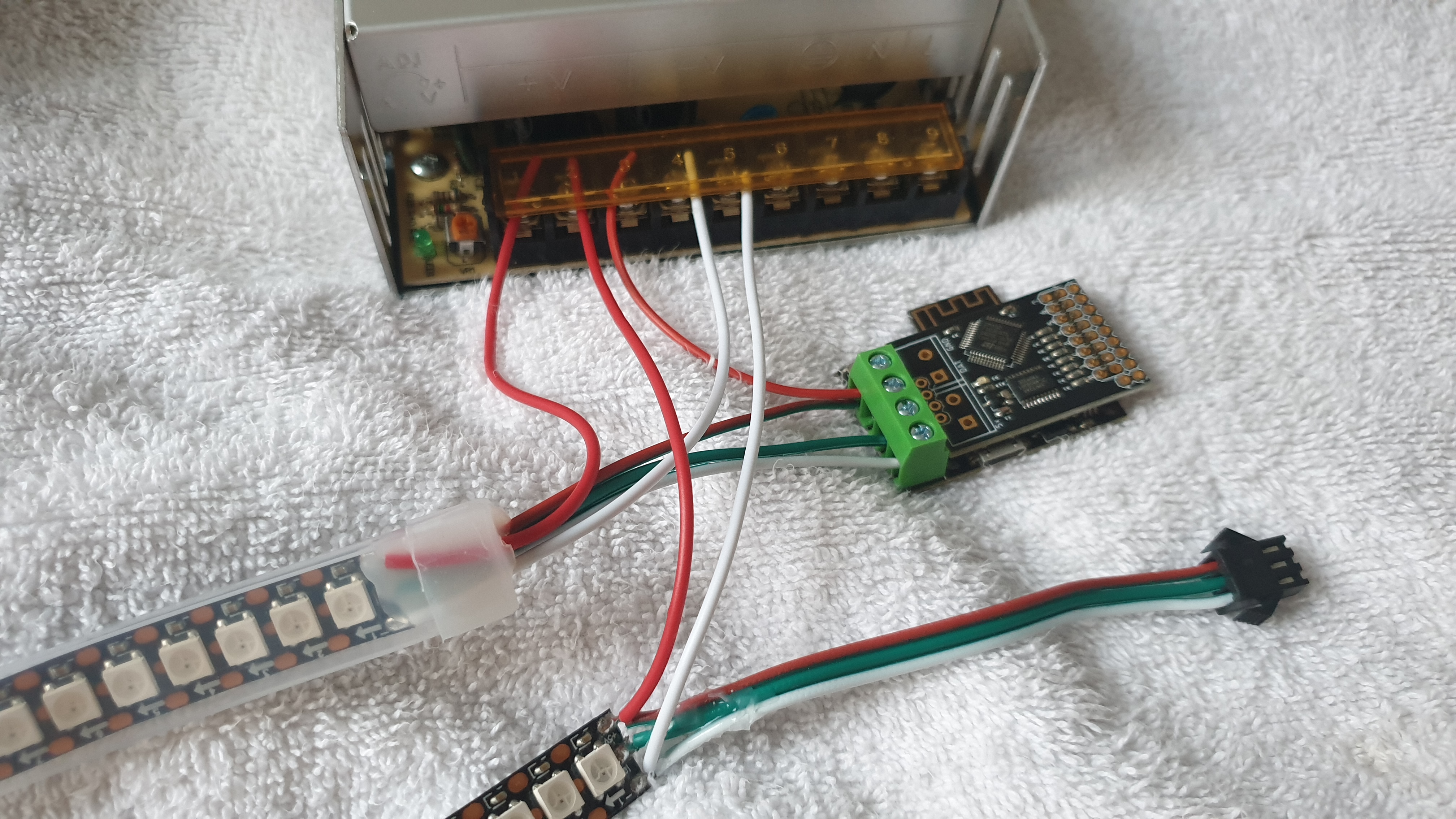
When using the output expander, it connects to Pixelblaze’s single output. You won’t connect your LEDs to that part anymore. The output expander’s input doesn’t come from the right side, that is where the sensor board can connect.
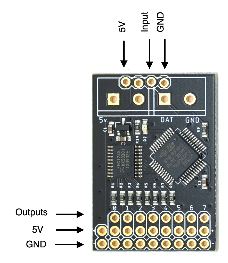
Here’s the hookup information (this should also be on the printout that came with the board):

Basically, you’ll flip it around 180 degrees, and connect it’s inputs to the output on Pixelblaze where you have a screw terminal. Then, your LEDs get their inputs from one of the 8 output channels marked 0-7 on the bottom (going off the picture). The data is the top row. You can distribute power as well, using the 2nd and 3rd rows.

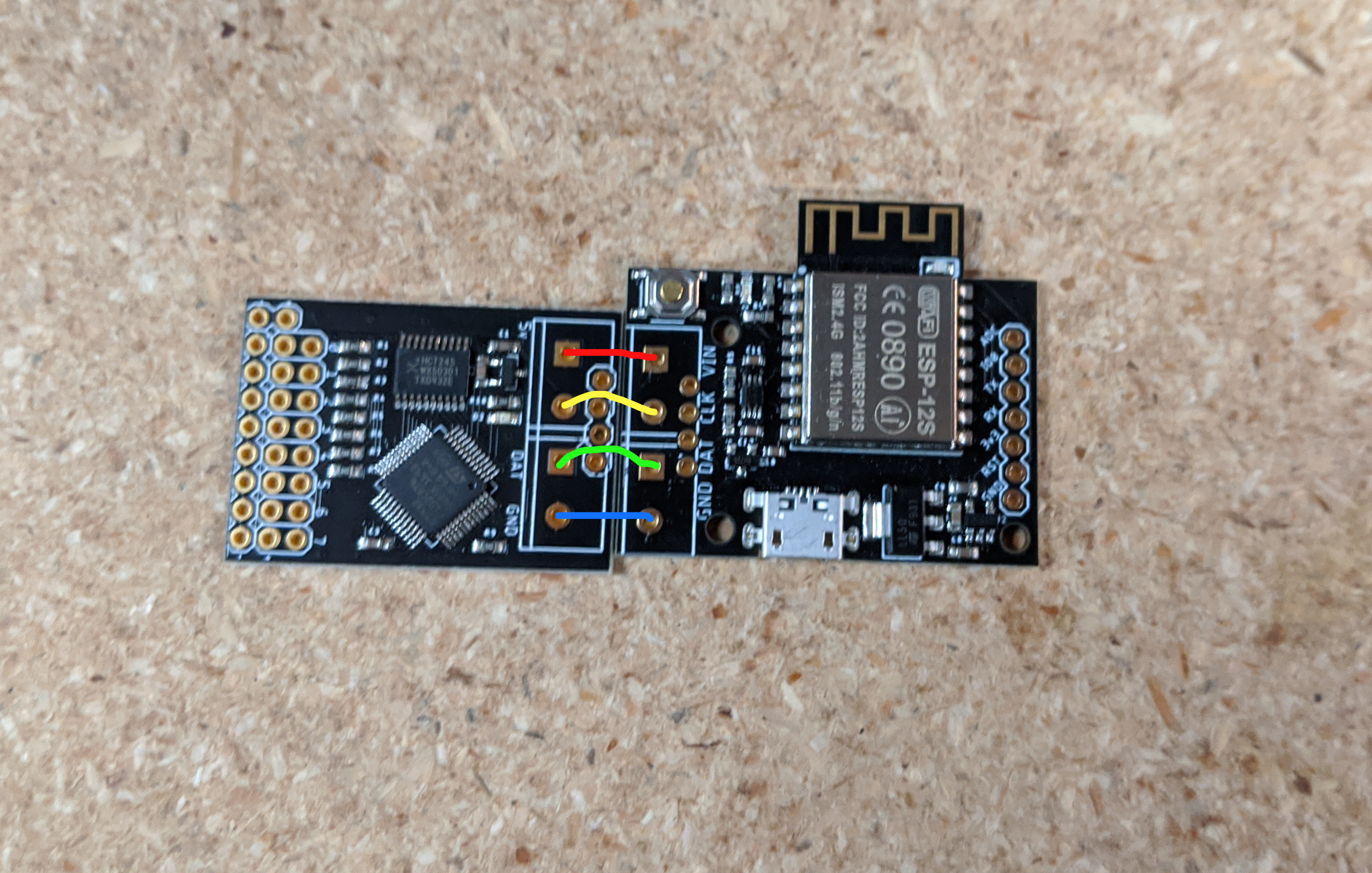
You can wire them up like this:

If you didn’t already have the screw terminal attached, I would say that you can overlap the 2 boards, the pins from the 0.2" and 0.1" headers line up just right. (Use a bit of wire through the holes to complete the sandwich connection)

It’s possible to do both, with the screw terminal going through both boards. While the data line can’t be used for LEDs, it can be a handy way to get power to the boards from a supply like yours. You can also provide power through the 2 extra pins on the output expander near the outputs, just to the left of output 0.

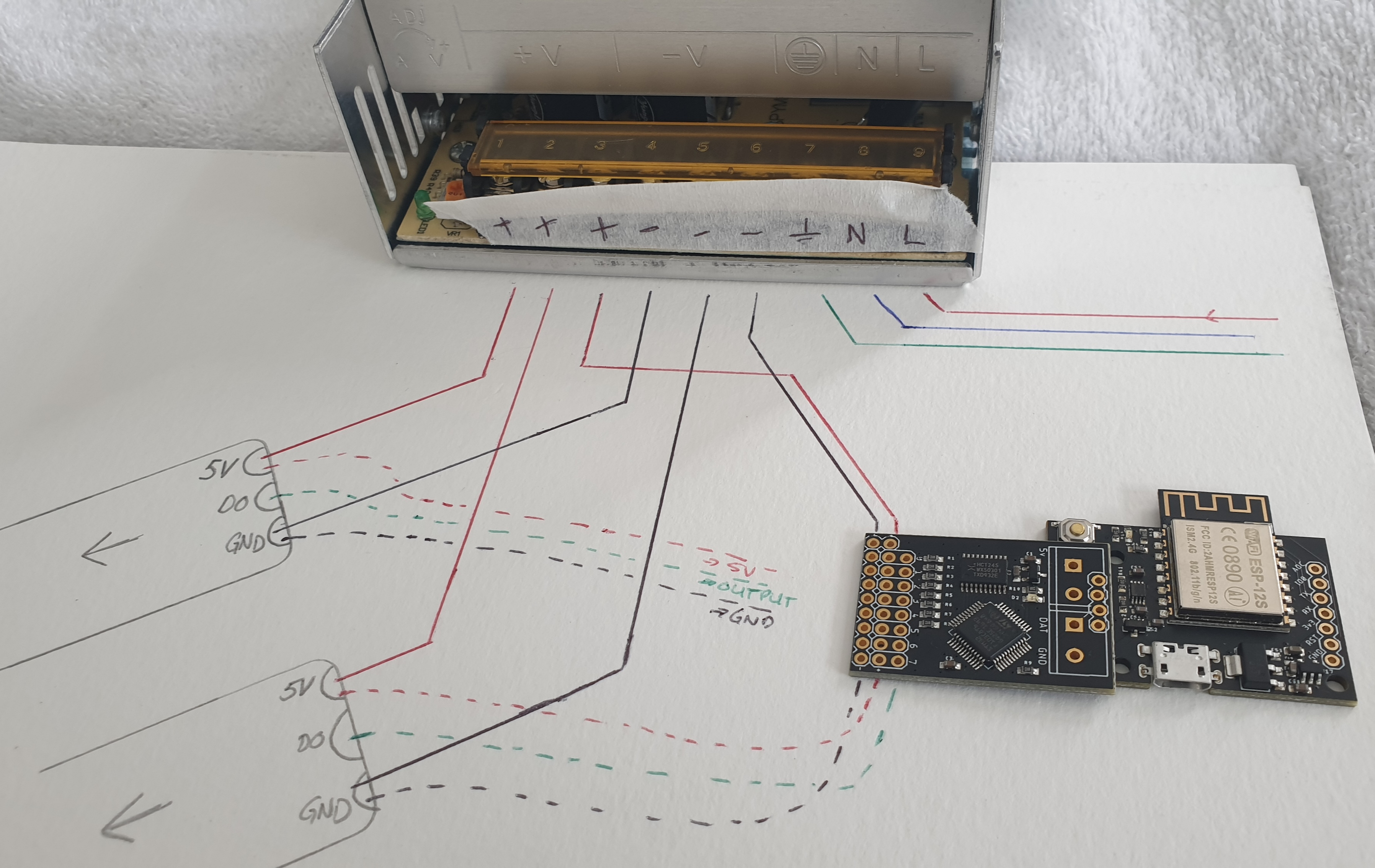
Here’s a color overlay showing how power is connected on the expander output rows:

Those same power signals also go to the input connection, and thus back to Pixelblaze, so you can back-feed power that way, or forward-feed it from the inputs and/or PB, whichever is most convenient. For high current (>3A or so) like your setup, wire up only GND and the data channel from the output expander to the LEDs, and provide +5v power for the LEDs directly from the power supply. You’ll still want to give Pixelblaze 5v through one of the connections mentioned above.

For power wiring, I like to reference this AWG chart:

https://www.powerstream.com/Wire_Size.htm

If each is pulling 120 watts, thats 24A. Your AWG12 is plenty thick. You can even drop to 14 gauge as long as each strip has it’s own pair of power wires. You’ll want to inject power along each of the 3 meter long strips so that the strip itself doesn’t have to carry the full 24A for all 3 meters.

1 Like

Thanks for the speedy response!
I’ve rearranged things and made a diagram that might be clearer aswell.
Does this make sense?

2 Likes

:+1::+1:

Great diagram! Yes that will work. You can drop the dashed red lines.

Strips get power directly :white_check_mark:
Pixelblaze and expander are powered and connected :white_check_mark:
Gnd (negative) and data from the expander to the LEDs :white_check_mark:

1 Like

SWEET!
Thanks for all the info.

Nominate for best diagram seen on forums in the last year.

3 Likes

Hi – This was very useful!

about the v+ from the output expander to the strip. the dashed red lines in the diagram.

The connectors i made for the expander 3 pin to the led matrix 3 pin JST each have all 3 lines wired up, in addition to the power feeding the panels and controller directly.

This extra v+ line is OK just not necessary? right?? Yes tell me i dont need to cut those lines after soldering them. :slight_smile:

Thanks!

The extra wires wouldn’t cause it to not work, but generally you want the main current flowing directly instead of through the small expander board when working with > 3A.

Worst case, if power were disrupted from the PS to the LEDs, then it would flow through the expander board. The current limits for the common 0.1" pin headers and connectors usually tops out at 3A. Beyond that things can get hot. If you solder wires directly you can do more, but the PCB itself would be a limitation at some point as well, and isn’t designed for very high current loads.

1 Like

Ah, thank you - that dis-connected the dots (pun intended) - it is a fail-safe configuration.