Yet another map assist

Hi!

I asked a similar question a while back but at the time I didn’t quite understand what I was asking. I got some help and it did help me understand how to create a map but I’m only now realizing that I actually need some assistance with rotating the side arrays in a walled cube.

The example code is, I think anyway, generating the array mapping based on some math. I haven’t been able to figure out how to manipulate that to rotate any given side of the cube. Nor can I figure how to remove said auto generating math to paste in my map to correctly orient the sides of my walled cube.

Can someone help me figure that?

Second question requiring the above to be working; does anyone have any interesting patterns utilizing the accelerometer to move light around a walled cube? I have a v3 with the sensor board attached. I’d like to have a few patterns on tap that take advantage of someone picking up the cube and rolling it around.

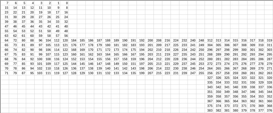
Here is a screenshot of panels:
@wizard Are you able to help? I need to rotate the orientation of specific sides of an 8x8 walled cube. I can’t figure it out.

I’m not really sure how to help, or what that screen shot is showing.

Getting the walled cube rotated right is hard. Best thing is to run a pattern that helps show alignment and alienation while fiddling with the map code. I do them one panel at a time.

Part of my issue is that I don’t know how to code and I’m having a hell of a time following the tutorials. I’m a hardware guy and generally copy and paste what I need code wise. I already know the orientation of my panels and how they need to be rotated; I mapped it all out as I was building it. I just have no clue how to make the PB software do it.

The screenshot of the spreadsheet is showing the order of the pixels from 0-383. It’s how I laid them out on the table before folding them up into a cube.

I’ve edited it a little to hopefully make it more legible. The starting LED for each panel is in red and bold. The panels are labeled with which panel they are as well as the orientation using the bottom panel as a reference. This layout is as if the 8x8 panels are LEDS down on a table. The bottom stays on the table and I fold up the sides to wrap them around the bottom panel. Then the top obviously goes on the top.

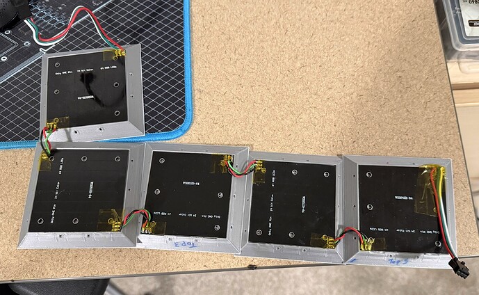
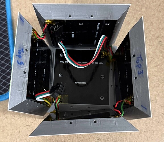
I could desolder the panels and rewire them with them all in the same orientation but that really creates a wiring mess. The way I have them now keeps my cube nice and clean. I’ve attempted to manipulate the order of the LEDs in the map to compensate but I haven’t been able to find anything that works correctly. As of now, any patter that would move horizontally across the side panels is broken up by panels 1 and 3 as those are in a different physical orientation to 2 and 4.

I can take actual photos or a video to show this better if it’s helpful. I feel like it’s just difficult to explain via text versus just showing it to someone.

That’s helpful. Still not 100% sure which way this folds up. If I printed that out, would the numbers face outwards, yeah? Then it would flip upside down since the bottom is first?

The map code lets you specify what you need for each panel.


map = map.concat(side([-1, 2, 0], [0, 0, 0]))

Would appear to map your first, bottom panel. Focus on the side() function. It takes two arrays, the first is which axis the panel pixel coordinates will travel. The -1 above is for rows first as x, in reverse order. Then the 2 is for columns of the panel are y. The next 0 means that the z is fixed (it’s the same for every pixel on the bottom panel).

The next array are for offsets. So eg top and bottom might be the same/similar for the first array but you’d add a z offset to the second array so that the top was raised.

In the example map code all the walls are spaced out a bit using a gap, I’ve removed that for the above example for clarity.

The panels are mounted in 3d printed plates. So in my diagram, the LEDs are face down and you’re looking at the back of the panels. The sides would fold up and away from you. Once folded up, you’d see the LEDs and wrap those sides around the bottom.

Thanks for the clarity. I’ll fiddle with those array values and see if I can get them to do what I need.

These will probably help immensely. Also of note, side 3 on the spreadsheet has the wrong arrow under it. Should be pointed to the left not up.

Following up on my progress.

I still don’t really have any idea how these numbers are changing the map. I know they are but I find it difficult to wrap my brain around how to change them to get any given side to function as intended. That said, I was able to just change them all around until I got what I wanted.

This is what I ended up with. Any 3D pattern I display works properly and wraps around the cube. It looks very cool. I haven’t tried all of them, but most 2D patterns aren’t displaying correctly. I’m not sure if this is expected or not. It seems like it should still process the map. Either way, 3D and 1D stuff looks the best and they work fine. Thanks for the help.

  var map = []
  var gap = .75
   map = map.concat(side([-2, -1, 0], [0,0,0])) //bottom
   map = map.concat(side([1, 0, 2], [0, 0, 0])) //side1
   map = map.concat(side([-0, 2, -1], [8, 0, 0])) //side2
   map = map.concat(side([-1, 0, 2], [0, 8, 0])) //side3
   map = map.concat(side([-0, -2, -1], [0, 0, 0])) //side4
   map = map.concat(side([1, 2, 0], [0, 0, 8])) //top
  return map
}

The map calculation is run by your browser JavaScript, so you could always

console.log(map)

before the return then look in your browser console to see the resulting map.

Edit: don’t forget that Pixelblaze will normalize this map!