I recently made a Pixelblaze powered LED dress that worked out pretty well. It survived a full night of abuse at a party without any problems at all, so I thought I’d share some of the build process here in case it helps others. But first, here’s the end result:

The Dress Itself
The dress was made from scratch but not by me; I confess I had a clothing-designer friend take care of the fabric and sewing side of things, so I’ll mostly focus on the electronics and wiring! it shouldn’t be too hard to adapt this project to an existing dress instead of making one from scratch though.
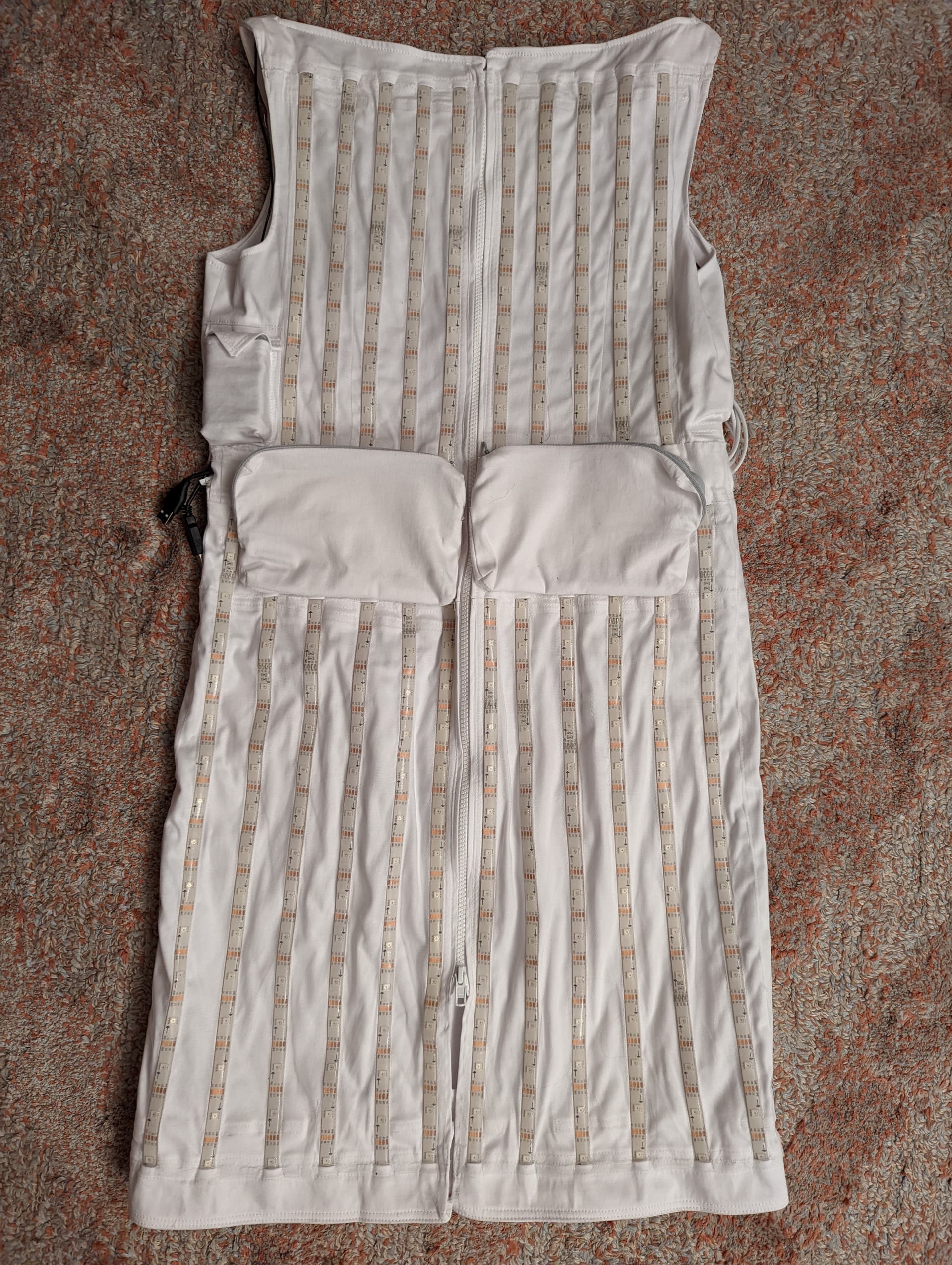
We deliberately decided to go with a dress design with sides that are quite straight. This made it easy to lay the LEDs out uniformly without too many curves or creases to deal with. A full length zip runs from top to bottom down the back of the dress, making it possible to unzip the entire dress lay the material out completely flat. This was hugely helpful when laying out and attaching the LEDs. If you’re using an existing dress that doesn’t open up completely like this, it would be very worthwhile to add a full length zip to it if you’re able to do so.
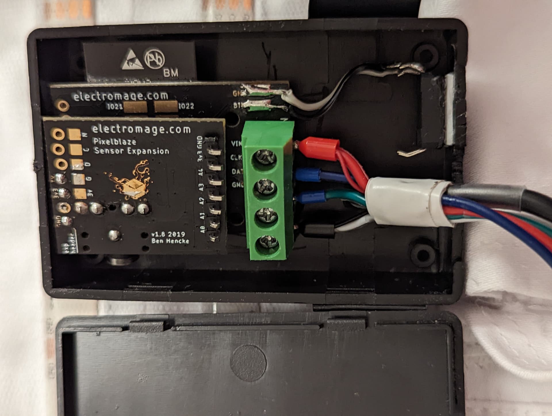
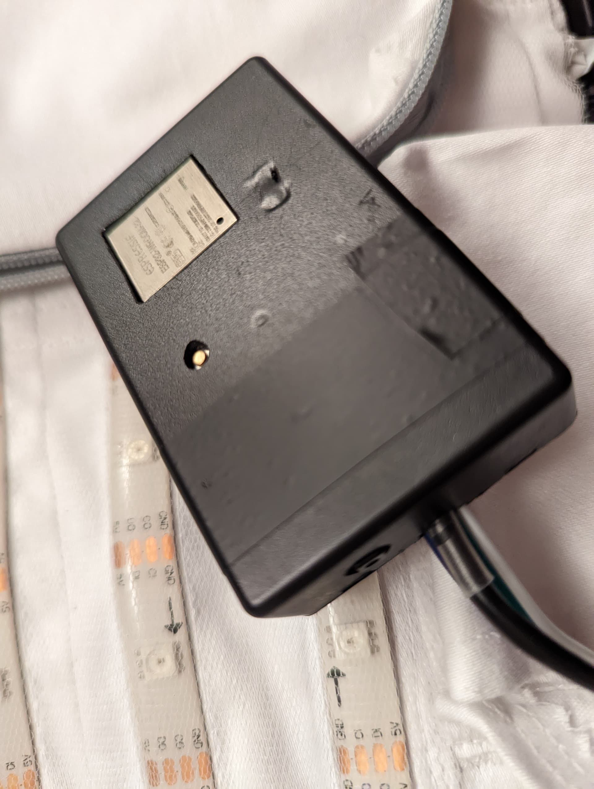
Pixelblaze Controller
The dress was of course powered by a Pixelblaze v3. There’s nothing particularly special about how this was wired up. I did include a sensor board and added a button to allow for switching patterns, but these are both optional. It was all housed in a small project box (so small I had to cut a couple of holes in it to fit everything in!), but the details don’t matter too much, any small box will do.
LEDs - Layout and Wiring
I created this spreadsheet to plan out how the LED strips would be laid out and how they would be wired up. The waist was deliberately kept free of LEDs to allow for better movement without risking breaking the LED strips. This did however mean a lot more wiring and soldering. Note that, because I didn’t have an expansion board, there is only one data/clock channel that runs the entire length of the LEDs. This isn’t ideal as any break in the data or clock wiring would result in, on average, half of the dress stopping working! Better would have been to have 8 different data channels to minimise any problems due to broken connections.
I chose to use APA102 / SK9822 LEDs to take advantage of the much finer graduations at low brightnesses compared to WS2812 LEDs, but WS2812s would work fine for this project too. I chose IP65 strips since the IP65 coating gives a good amount of extra rigidity compared to IP20 strips. This significantly reduces the chance of them breaking while the dress is being worn. I also find the IP65 strips to be easier to work with than IP67 covered ones.
Mapping
I chose to map the dress as a 2D grid. This is because the majority of the patterns I wanted to use were 2D anyway, and I knew from past experience that they would look better when mapped onto a 2D grid (effectively an “unrolled” cylinder) rather than onto a cylinder itself.
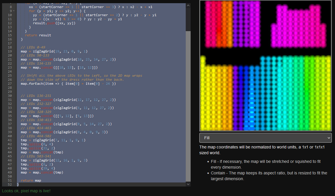
One key consideration with using a 2D grid that wraps around like this is where the edges of the grid lie on the physical costume. If I was to create a 2D grid map that matched up exactly with the spreadsheet (with the left and right edges of the grid matching up with the zip at the back of the dress), any patterns that didn’t “wrap” around seamlessly across left and right edges of the grid would cause a visible break in the pattern at the back center of the dress. So instead of doing this, I offset the map so that this “seam” ran down under one arm. This resulted in any visual artifacts due to this seam being much less visible to observers. It also made it easier to mirror some patterns front and back (rather than have them stretch all the way around the whole dress).
Here’s the mapping code I used:
function (pixelCount) {
  // Creates a zigzag matrix covering the area (x1, y1) - (x2, y2), with the
  // strips running vertically.
  // startCorner: 1 = top left, 2 = top right, 3 = bottom left, 4 = bottom right
  function zigZagGrid(x1, x2, y1, y2, startCorner) {
    var result = []
    for (x = x1; x <= x2; x++) {
      xx = (startCorner == 1 || startCorner == 3) ? x : x2 - x + x1
      for (y = y1; y <= y2; y++) {
        yy = (startCorner == 1 || startCorner == 2) ? y : y2 - y + y1
        yy = ((x - x1) % 2 == 0) ? yy : y2 - yy + y1
        result.push([xx, yy])
      }
    }
    return result
  }

  // LEDs 0-49
  map = zigZagGrid(19, 23, 0, 9, 1)
  // LEDs 50-133
  map = map.concat(zigZagGrid(18, 23, 14, 27, 2))
  // LEDs 134-135
  map = map.concat([[18, 13], [18, 12]])

  // Shift all the above lEDs to the left, so the 2D map wraps
  // down the side of the dress rather than the back.
  map.forEach(item => { item[0] = item[0] - 24 })


  // LEDs 136-231
  map = map.concat(zigZagGrid(12, 17, 12, 27, 2))
  // LEDs 232-327
  map = map.concat(zigZagGrid(6, 11, 12, 27, 2))
  // LEDs 328-329
  map = map.concat([[5, 12], [5, 13]])
  // LEDs 330-413
  map = map.concat(zigZagGrid(0, 5, 14, 27, 2))
  // LEDs 414-463
  map = map.concat(zigZagGrid(0, 4, 0, 9, 3))
  // LEDs 464-502
  tmp = zigZagGrid(7, 11, 1, 9, 1)
  tmp.splice(0, 4)
  tmp.splice(31, 2)
  map = map.concat(tmp)
  // LEDs 503-541
  tmp = zigZagGrid(12, 16, 1, 9, 3)
  tmp.splice(8, 2)
  tmp.splice(39, 4)
  map = map.concat(tmp)

  return map
}
You can see in Pixel Mapper screenshot below that this results in the grid edges aligning with the side of the dress rather than back center:
Powering the LEDs
I already knew I wanted to use 2 x 20,000mAh battery packs, each with 2 USB-A ports, hence why I allowed for four different powered regions shown in the spreadsheet. The Pixelblaze itself just piggybacked its power off the end of one of the USB-A power connections, no extra USB connection was required.
The 2 x 20,000mAh battery packs is probably more power than you will need. It gave a total runtime of about 10 hours at 60% brightness (plenty bright enough!).
Note that choosing the right power source(s) can be tricky. Some powerbanks can’t deliver enough current for this many LEDs, especially true of smaller capacity powerbanks. Some powerbanks shut down if there isn’t enough power draw (such as when a pattern briefly goes blank or doesn’t light up many LEDs. If you’re lucky the powerbank may have a way to override this, otherwise you might have to add a resistor or other small load to prevent the powerbank shutting down.
I knew the powerbanks I had chosen were up to the task but unfortunately they’re old and no longer available so there’s no point in me recommending them. All I can suggest is look very carefully at the specs of any powerbank to make sure it can deliver around 2.4A or more on both USB-A channels at the same time, or see this thread for some other ideas such as using USB-C PD decoys to get additional power via USB-C. You could also use your own setup using lithium batteries and buck converters (something I’ve done successfully in other similar projects).
The Wiring
Now that the basic design was done, it was time to start building! My friend made a mock-up dress that I used as a template for laying out the LEDs (she created the real dress later, once I was happy the design was going to work OK). I marked out on the mock-up where the strips would go, then cut the LED strips to length and checked they would lay out correctly.
Next came the big job of soldering them all up:
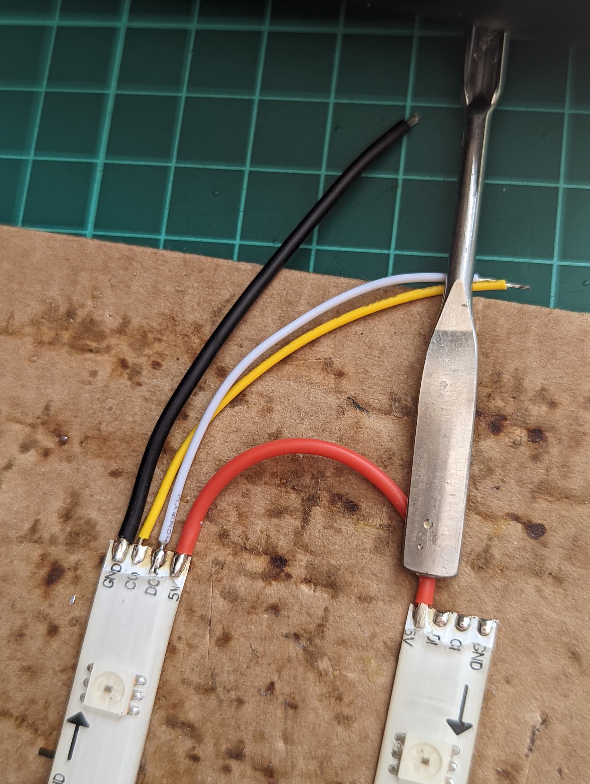
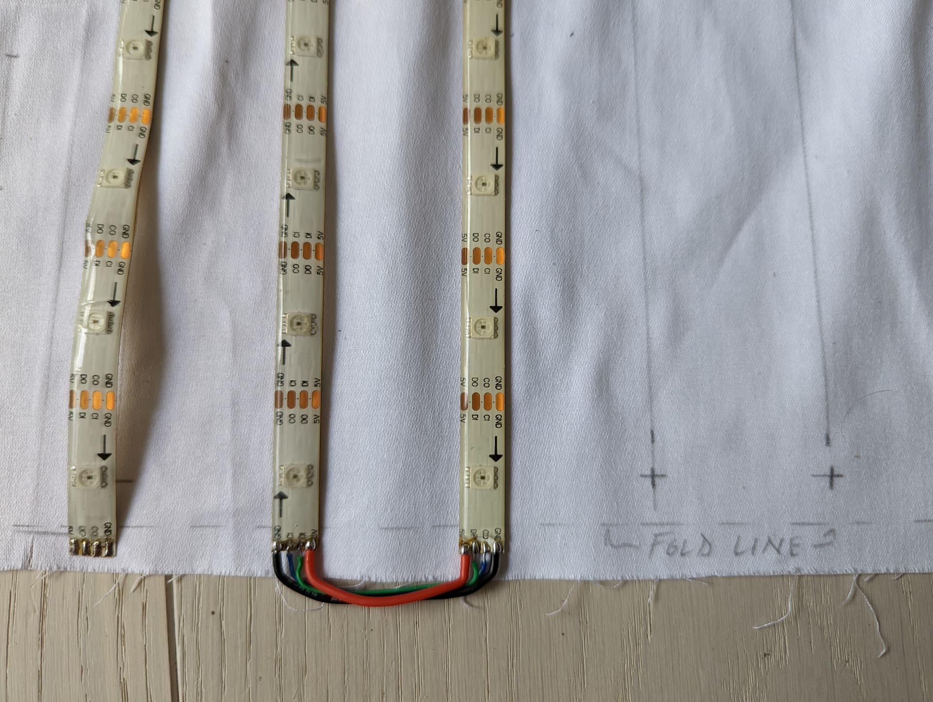
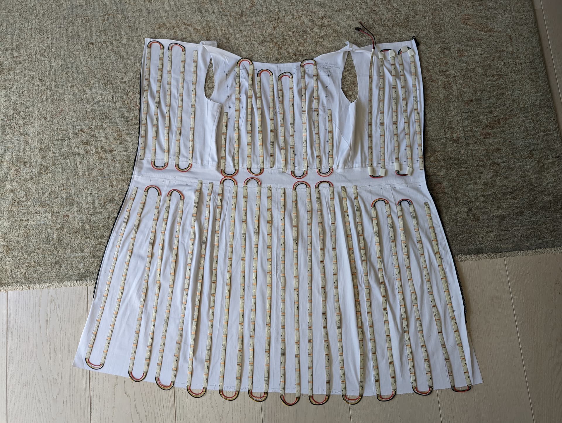
In total I created 8 separate zig-zags of connected strips, two for each power region (one for above the waist, one below)
I tested each of these individually:


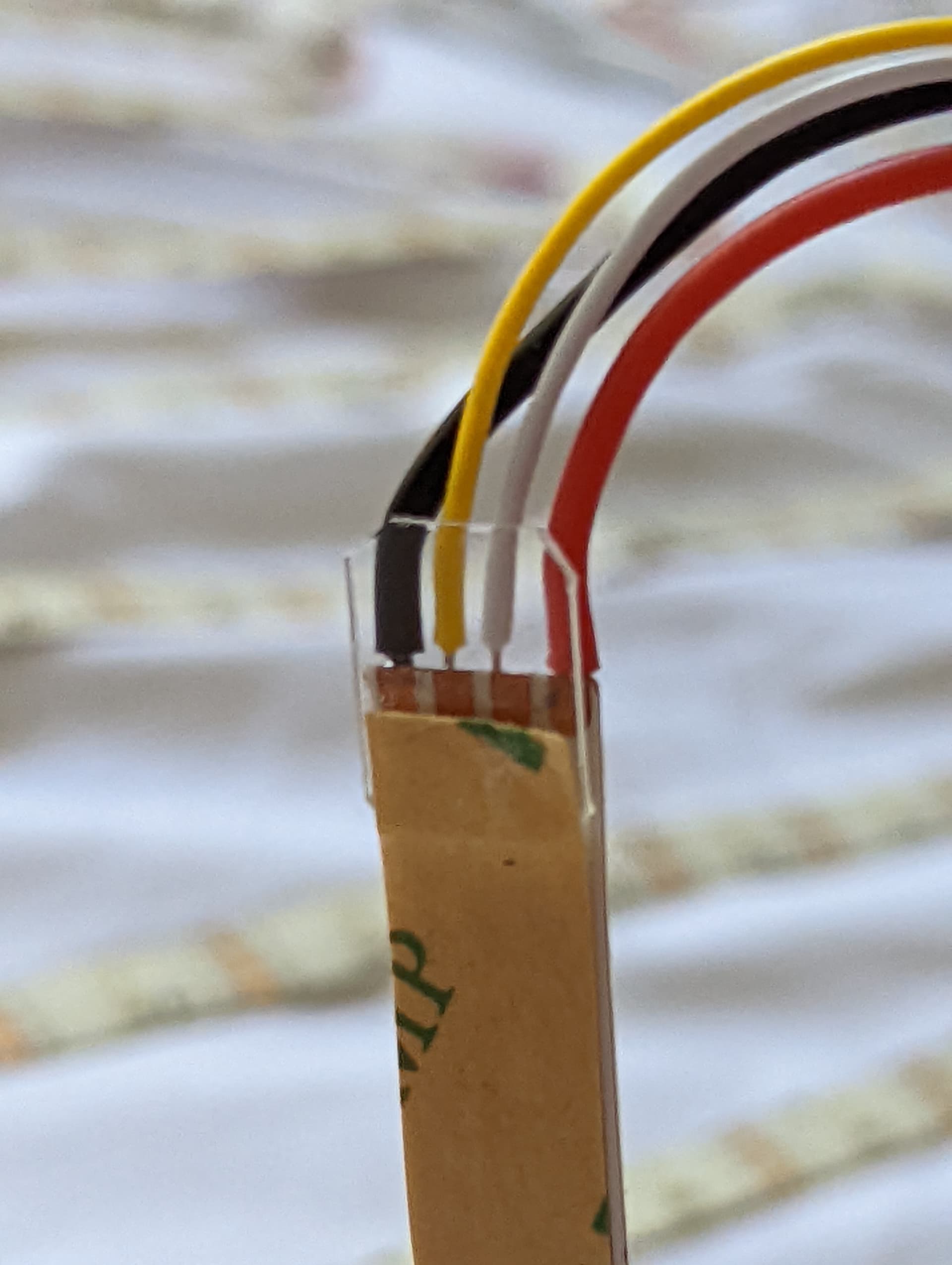
Once I’d tested them, I then glued a small square of clear plastic to give some extra backing strength to the solder joints:
After that I hotglued over the solder. Once that cooled I applied 10mm heat shrink over the hotglue using a heat gun. The heat gun would remelt the hotglue as the heatshrink closed around it, resulting in a nice snug encasing of the solder joint that made for a very reliable connection. Sometimes the hotglue spilled out from under the heatshrink a bit, I just trimmed off any excess with small scissors.
USB Wiring
To connect the powerbanks to the LEDs, I took four old micro/mini USB cables and cut off the micro/mini connector ends. Next, the outer insulation was stripped back from the cut end of each cable, exposing four wires - black, red, white and green. The white and green were soldered together then folded back and covered in heat shrink. The black (ground) and red (positive) wires were used to provide 5V power to the LED strips, one USB cable per power region (as shown on the spreadsheet). The black and red wires should ideally be connected to both ends of a power region (for example, to LEDs 328 and also to 463 in the spreadsheet. This helps reduce any voltage drop, and also provides some redundancy in case one of the power connections breaks during use.
It is important to note that everything (both powerbanks plus the Pixelblaze) must share a common ground, so the ground wires are connected between the power regions (for example, from LED 327 to 328). You must however be careful not to connect up the red +5V wires between power regions, each must have separate +5V connections!
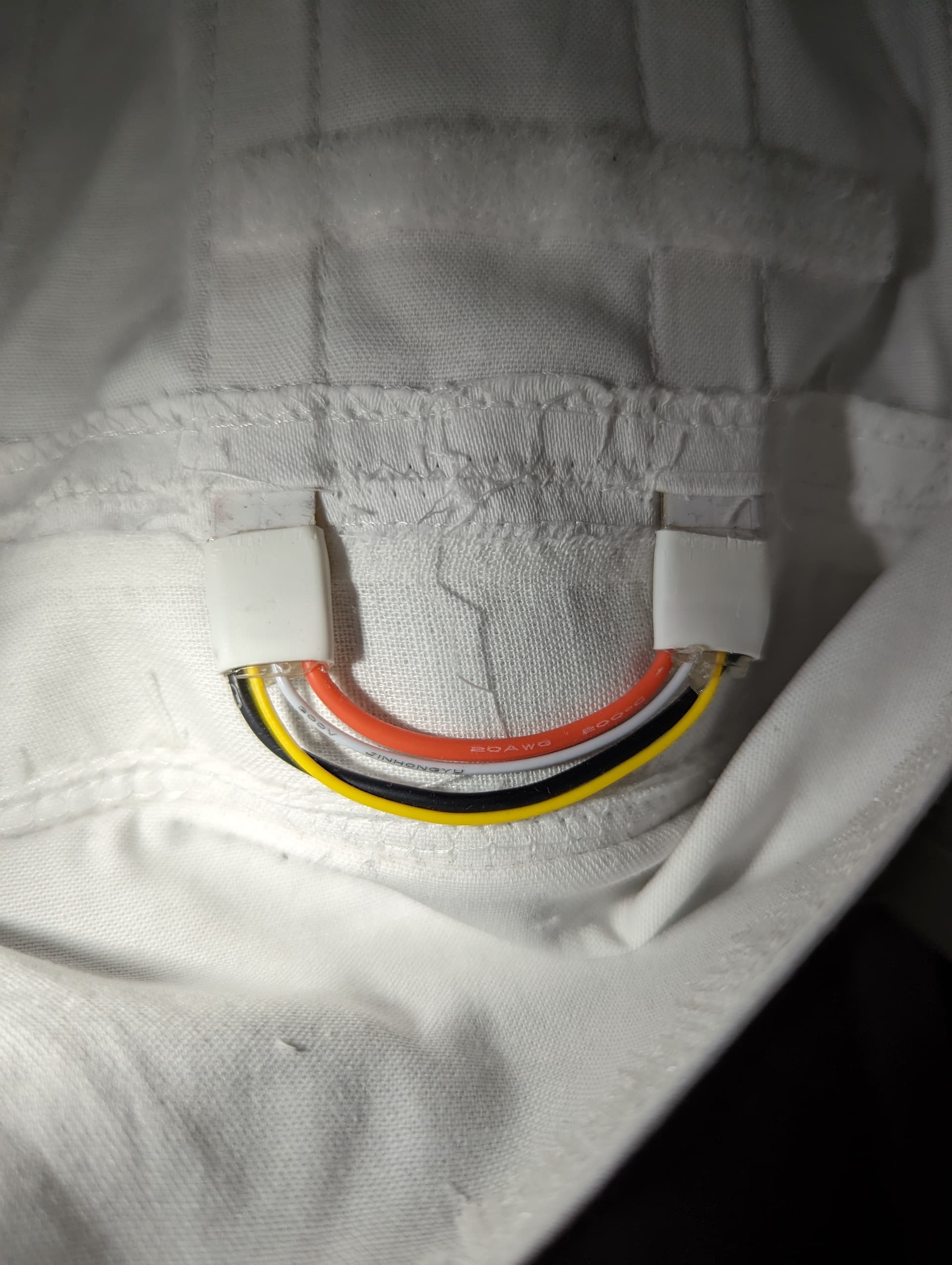
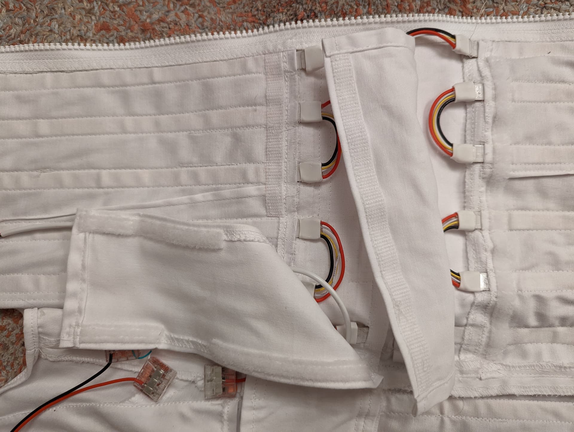
Note that not all the power connections were soldered directly to the LEDs. Instead, connector blocks similar to these were used in a few places to allow some of the wiring to be easily detached. This made it easier to adjust and test the wiring, figure out how to route it, and attach the LEDs to the fabric. Originally the plan was to eventually remove the blocks and solder these connections up properly, but the blocks worked very well and didn’t get in the way, so they became a permanent fixture.
Adding the LEDs to the Dress
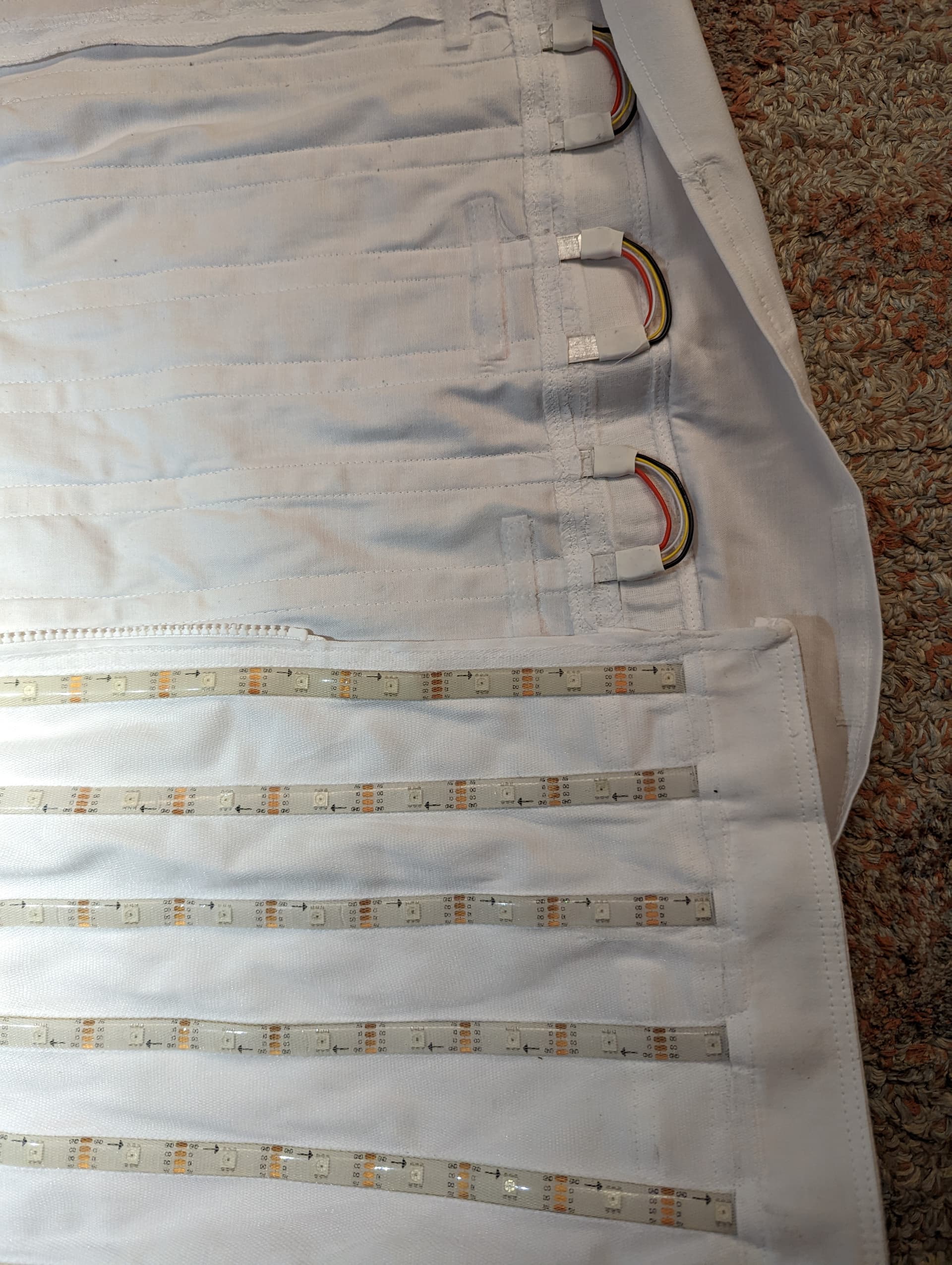
Now that the wiring was taken care of, it was time to attach the LEDs to the dress. This was done by sewing a fine mesh over top of the strips to hold them in place. The paper backing that covers the strip’s adhesive was not removed, though you could do so if you wanted to. You could also glue the strips on instead of covering with mesh, though this gets a bit messy and makes it trickier to repair should one of the strips break.
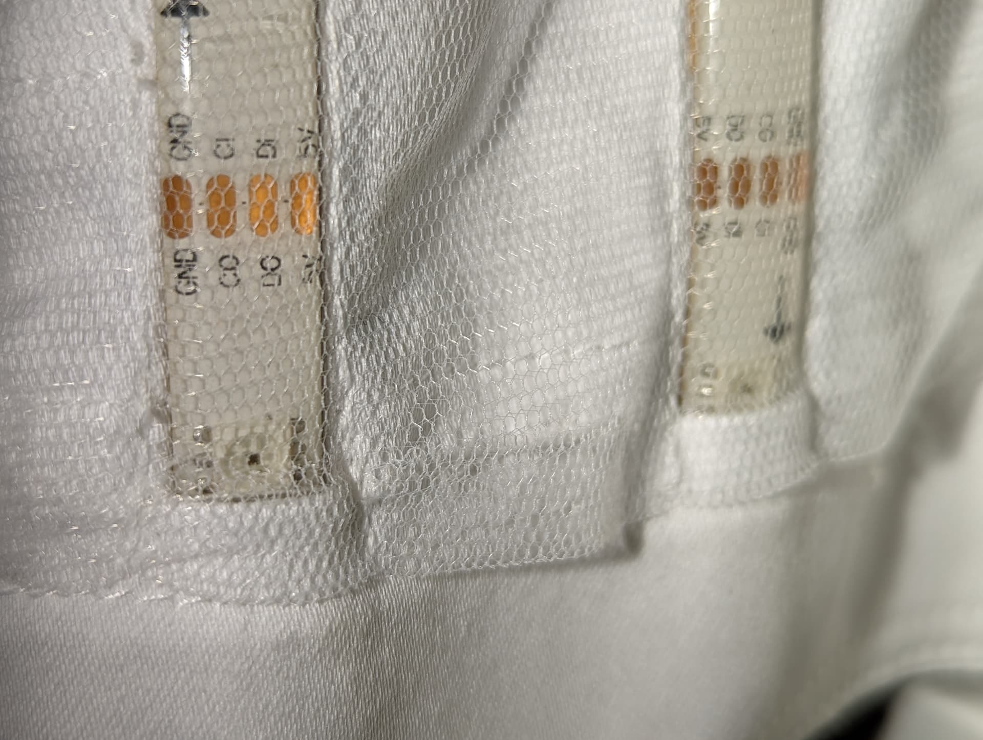
At the ends of the strips an additional layer of material was sewn over the top to hide all the wiring. There was also an extra flap of material added with some velcro, so the wiring could be covered up completely to tidy things up and prevent it catching on anything, but still provide easy access if any repairs were needed.
Mounting the Battery Packs and Pixelblaze
Two pouches were added to the back of the waist for the battery packs, and a smaller pocket was added just above the waist under the arm to house the Pixelblaze box. The four USB cables were run through holes, two to each battery pack.

It’s not shown in any of the photos here, but there is also a completely separate additonal thin layer that is worn over top of everything to prevent the mesh getting caught in anything, plus to provide a bit of a diffusion effect.
Whew! That’s about it really, though of course if there’s anything you want me to explain in more detail please let me know and I’ll try to help.