Mapping matrix displays

Hi all, Hoping to find some tips about orienting matrix panels for ease of mapping and optimal use both with a 2d map and without a map or using the RING map.

I’m using 4 of the 64 LED 8x8 panels from electromage

They are being arranged into a 2x2 grid and experimenting with two arrangements.

  1. One where they are all arranged / oriented in the same direction. All 4 8x8 matrices with the Label down, pixel zero oriented in the same relative spot on all 4 panels.

  2. 2 matrix aligned top to bottom and inverted left to right. 2 on the left are sequential, then bottom right, and then top right. With the panels on the right upside down relative to the panels on the left.

i dont really think i have a proper map for either arrangement. (just using the default map and UN-commentating the line to make it zig zag and changing the width to 16) which i think is not quite right for either case… But

I seem to like #2 better - since then the natural pixel arrangement sweeps counterclockwise around a circle so to speak. and the distance between connectors is closer together and the ring map seems to work fairly well given the counter clockwise or Clockwise arrangement of pixel index depending on the ID of the panel 1,2,3,4.

it seems there are 2 methods with 2 variants to arrange clockwise or counterclockwise.

I’m still struggling a bit with following the mapping code, so not sure which would be better easier to map. ( i guess at some level its all code and once written its easy)

I like #2 better where 2 of the panels are inverted because it works fairly well with either NO map or a RING map with the patterns that dont like 2d or 3d maps.

Enough of what i have tried…

How would you arrange the panels in a 2 x 2 grid?

thanks for any insights or pointers!

regards
scott-
1 Like

Hey Scott!

Since I’m staring at mine right now, I’m going to quickly give you something that works. I’m not going to claim it’s the most logical layout, but it’s correctly mapped!

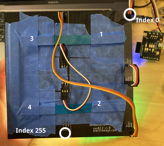
Please forgive the popsicle sticks and blue tape. The numbers show the panel wiring order which will correspond to each of the 4 distinct blocks in the map generation code below.

Here is the map I’m using:

function (pixelCount) {
  const width = 8
  var map = []
  for (i = 0; i < pixelCount / 4; i++) {
    y = Math.floor(i / width)
    x = i % width
    x = y % 2 == 1 ? width - 1 - x : x // zigzag
    map.push([x, y])
  }
  for (i = 0; i < pixelCount / 4; i++) {
    y = Math.floor(i / width)
    x = i % width
    x = y % 2 == 1 ? width - 1 - x : x // zigzag
    map.push([x, y + width])
  }
  for (i = 0; i < pixelCount / 4; i++) {
    y = Math.floor(i / width)
    x = i % width
    x = y % 2 == 1 ? width - 1 - x : x // zigzag
    map.push([x + width, y])
  }
  for (i = 0; i < pixelCount / 4; i++) {
    y = Math.floor(i / width)
    x = i % width
    x = y % 2 == 1 ? width - 1 - x : x // zigzag
    map.push([x + width, y + width])
  }
  return map
}

Once you get used to writing code in render2D() and consuming x & y in 0…1 ‘world units’ you’ll rarely care about index or how you wired it up. Hope this helps!

Jeff

2 Likes

HI Jeff- thanks! love the materials. This helps - and sure i could just take that and it would work better than what i had. but think I’m on the edge of the ah ha…about the world units and mapping…

I dont understand looping through only 1/4 of the pixel index space 4 times
i do understand that’s all 256 pixels.
and what helps is seeing what is being pushed onto the map.
that i think do understand as the relative position of the pixel in the world map. each of the 4 sections is offset based on the width (convenient its a square eh? :slight_smile: )

but what i dont understand is the mapping of the pixels to the world unit, when using only 1/4 of the total pixel count the same 1/4 , 4 times.

1 Like

OH, the index of the MAP element is the physical pixel index, that’s the “link” i was missing… I get it now. i think. doah!

2 Likes

Jeff your map was super useful to help me realize the mapping for 2D now onto 3D…

the fibonacci display really shows some sick 3d and i dont quite fully understand it yet, but the visual effect is 3d like. just simply using the default sample really basic getting started here is your first rotating color index pattern is sick on the fibonacci 256 layout, it looks 3D. like one of those stereoscopic pictures with depth. ( i presume is a result of the combination of the 3d map, pixel color / intensity, diffuser and its dimishiment of the light, along with the physical pixel layout all working together in some magical harmony.) it was the first thing my wife has seen so far (AND she has been very very tolerant of the many MANY projects and has even allowed a few to “stay”) where she said hey, i want one of those…

I’m working on a map for a 5 sided cube now that i figured out the 2d matrix. 4 sides are good but just need to get that one panel i EPOXIED on backwards mapped correctly.

and in case it helps someone else, here is the map for Option #2,

(POV from the back) Panel 1 is top left, panel 2 is bottom left, Panel #3 is bottom right upside down, and panel #4 is top right upside down. (my 1,2,3,4, using the picture as a reference is 3,4,2,1 with my 3 and 4 upside down)

i seem to like this layout better.

Kit is bouncing in a semi circle rather than top to bottom on each side. and the index walk walks in a connected chain of pixels…that simulates a ring…

function (pixelCount) {

const assycount = 4
const width = 8
const size = pixelCount / assycount

var map = []

for (i = 0; i < size; i++) {

y = Math.floor(i / width)

x = i % width

x = y % 2 == 1 ? width - 1 - x : x // zigzag

map.push([x + width, y])

}

for (i = 0; i < size; i++) {

y = Math.floor(i / width)

x = i % width

x = y % 2 == 1 ? width - 1 - x : x // zigzag

map.push([x + width, y + width ])

}

for (i = size-1; i > -1; i–) {

y = Math.floor(i / width)

x = i % width

x = y % 2 == 1 ? width - 1 - x : x // zigzag

map.push([width - x -1 , y + width])

}

for (i = size-1; i > -1; i–) {

y = Math.floor(i / width)

x = i % width

x = y % 2 == 1 ? width - 1 - x : x // zigzag

map.push([width - x -1, y])

}

return map

}

1 Like

Hi folks,
A bit late to the party, but I had an unusual arrangement of 8x8 panels and needed to map them. I came up with this system, which should allow all kinds of arbitrary arrangements of these or other panels of any width, height, and including rotations!

function (pixelCount) {
  //enable zigzag if every other LED row travels in reverse
  //if they are all straight across, disable it
  zigzag = true
  
  //roate a point (x, y), along a center (cx, cy), by an angle in degrees
  function rotate(cx, cy, x, y, angle) {
    var radians = (Math.PI / 180) * angle,
        cos = Math.cos(radians),
        sin = Math.sin(radians),
        nx = (cos * (x - cx)) + (sin * (y - cy)) + cx,
        ny = (cos * (y - cy)) - (sin * (x - cx)) + cy;
    return [nx, ny];
  }

  //create a set of coordinates for a matrix panel
  // sized (w, h), rotated by an angle, and offset by (sx, sy)
  function panel(w, h, sx, sy, angle) {
    var x, x2, y, p, map = []
    for (y = 0; y < h; y++) {
      for (x = 0; x < w; x++) {
        //for zigzag, flip direction every other row
        if (zigzag && y % 2 == 1)
          x2 = w - 1 - x
        else
          x2 = x
        p = rotate((w-1)/2, (h-1)/2, x2, y, angle);
        p[0] += sx
        p[1] += sy
        map.push(p)
      }
    }
    return map;
  }

  //assemble one or more panels
  var map = [];

  map = map.concat(panel(8, 8, 0, 0, 0))
  map = map.concat(panel(8, 8, 0, 8, 0))
  map = map.concat(panel(8, 8, 8, 8, 0))
  map = map.concat(panel(8, 8, 8, 0, 0))

  return map
}

Here’s my funky panel map in action:

Nov-04-2020 12-16-10

In this kind of setup:

1 4
2 3

The rotation is really only intended to work with 90° increments, it positions the panels from the top left corner before rotation along the center. However, these helper functions could be adapted for arbitrary angles and positioning.

3 Likes

May I ask what kind of electrical connectors you bought, and where you got them?

Hi! These are female-female servo connectors. If you can wait a week or two for shipping, I’ve purchased a variety of lengths from HobbyKing.

The pins soldered in are standard 0.1” headers. I tried both, and the right-angle ones are nice.

1 Like

Can you please explain what the first four numbers represent. I did figure out the last number controls the rotation, Thanks!

Hi @Ubiquitous! Check out the definition of panel() a little higher up in the code. You can see it’s the panel’s size and location.

2 Likes

Thanks, I totally missed that!

So in what circumstances would one want to change the offset? I’m a bit curious.

EDIT: I think I just realized why. If I’m thinking correctly it’s to account for the panel to the side of another.

Hi @Ubiquitous,
If you have more than 1 panel you are trying to assemble, add an offset so that they don’t overlap. The order that you add them to the array has to match with the pixel indexes, and specifying the offset for each gives you the flexibility to add panels in any order for any physical location.

In the example include with that post, I have 4 panels in an unusual arrangement. The first starts at the top left corner at (0, 0), the next is down 8 pixels at (0, 8). The third is both down and to the right by 8 pixels at (8, 8). The fourth is just to the right of the first at (8, 0).

The offsets are the 3rd and 4th arguments, as show here:

1 Like

6 posts were split to a new topic: Performance with 2048 LEDs on V2/V3

I’m doing a project using a number of 8*32 matrices daisy-chained together to make a large panel, and because of the way the connectors are oriented it’s necessary to flip every other one around (starting with the first panel, unfortunately, so X=0 is actually pixel 7).

If anyone else wants to do something similar, here’s a variation of @wizard’s mapping function above that handles row-zigzags within panel-zigzags:

function (pixelCount) {
  //set zigzag to true if every other LED row travels in reverse
  //if they are all straight across, set it to false
  zigzagFirst = false
  zigzagRows = true
  zigzagPanels = true
  
  //rotate a point (x, y), along a center (cx, cy), by an angle in degrees
  function rotate(cx, cy, x, y, angle) {
    var radians = (Math.PI / 180) * angle,
        cos = Math.cos(radians),
        sin = Math.sin(radians),
        nx = (cos * (x - cx)) + (sin * (y - cy)) + cx,
        ny = (cos * (y - cy)) - (sin * (x - cx)) + cy;
    return [nx, ny];
  }

  //create a set of coordinates for a matrix panel
  //sized (w, h), rotated by an angle, and offset by (sx, sy)
  function panel(w, h, sx, sy, angle) {
    var x, x1, x2, y, y1, p, map = []
    for (y = 0; y < h; y++) {
      if (zigzagPanels) y1 = h - y - 1; else y1 = y;
      for (x = 0; x <w; x++) {
        //  Some panels eg. 8x32 start with first row order swapped
        if (zigzagFirst) x1 = w - x - 1; else x1 = x;
        //for zigzag, flip direction every other row
        if (zigzagRows && y1 % 2 == 1) x2 = w - 1 - x1; else x2 = x1;
        p = rotate((w-1)/2, (h-1)/2, x2, y1, angle);
        p[0] += sx
        p[1] += sy
        map.push(p)
      }
    }
    return map;
  }

  //assemble one or more panels
  var map = [];

  map = map.concat(panel(8, 32, 0, 0, 0))
  map = map.concat(panel(8, 32, 8, 0, 180))
  map = map.concat(panel(8, 32, 16, 0, 0))
  map = map.concat(panel(8, 32, 24, 0, 180))
  // and so on...

  return map
}
3 Likes