Using Pixel Mapper to Invert Strip

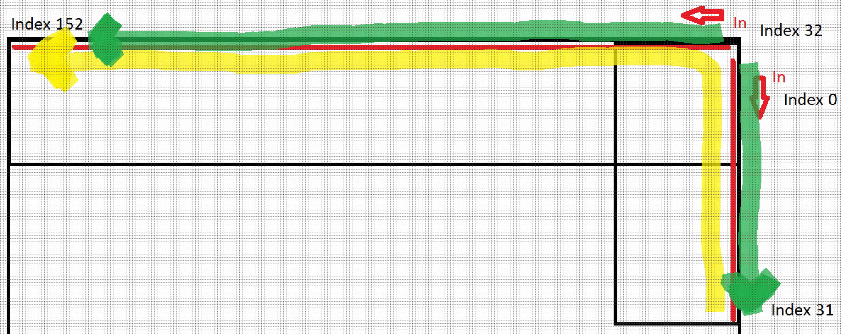
I’ve wired up some strip lighting underneath the railings (denoted as the red lines in the graphic below) leading downstairs at my house using a PixelBlaze and output expander, the railing forms an L shape as it bends around a corner. I’m currently using two of the expander channels (with more to come later). I’ve tweaked the starting index on the expander configuration to account for the two strips. Due to some constraints with the existing construction, the data input wiring comes into both strips at the corner of the L as shown in the image below (noted as “in”). I’m having some issues with render2D and 3D; ideally, I want the strips to act as a single continuous strip, flowing in the direction of the yellow highlighted line. However, when testing basic 2D and 3D render functions, the strips light as shown by the green highlighted line. Basically, I’m looking for a software solution for inverting one of these strips for 2D and 3D renders since I’m stuck with the physical layout due to existing drywall. I’m fairly confident this is a pixel mapping issue, but I haven’t had any luck with my edits flipping the order of the JSON array. Any pointers as to where I’m going wrong would be appreciated.

As a basic test, I’m using the following pattern

export function beforeRender(delta) {
  t1 = time(.1)
}

export function render3D(index, x, y, z) {
  h = t1 + index/pixelCount
  s = 1
  v = 1
  if (z < .4){
    hsv(h, s, v)}
}

For reference here’s my JSON Array

[[0,0,62], [0,1,60], [0,2,58], [0,3,56], [0,4,54], [0,5,52], [0,6,50], [0,7,48], [0,8,46], [0,9,44], [0,10,42], [0,11,40], [0,12,38], [0,13,36], [0,14,34], [0,15,32], [0,16,30], [0,17,28], [0,18,26], [0,19,24], [0,20,22], [0,21,20], [0,22,18], [0,23,16], [0,24,14], [0,25,12], [0,26,10], [0,27,8], [0,28,6], [0,29,4], [0,30,2], [0,31,0], [0,81,0], [2,82,0], [4,83,0], [6,84,0], [8,85,0], [10,86,0], [12,87,0], [14,88,0], [16,89,0], [18,90,0], [20,91,0], [22,92,0], [24,93,0], [26,94,0], [28,95,0], [30,96,0], [32,97,0], [34,98,0], [36,99,0], [38,100,0], [40,101,0], [42,102,0], [44,103,0], [46,104,0], [48,105,0], [50,106,0], [52,107,0], [54,108,0], [56,109,0], [58,110,0], [60,111,0], [62,112,0], [64,113,0], [66,114,0], [68,115,0], [70,116,0], [72,117,0], [74,118,0], [76,119,0], [78,120,0], [80,121,0], [82,122,0], [84,123,0], [86,124,0], [88,125,0], [90,126,0], [92,127,0], [94,128,0], [96,129,0], [98,130,0], [100,131,0], [102,132,0], [104,133,0], [106,134,0], [108,135,0], [110,136,0], [112,137,0], [114,138,0], [116,139,0], [118,140,0], [120,141,0], [122,142,0], [124,143,0], [126,144,0], [128,145,0], [130,146,0], [132,147,0], [134,148,0], [136,149,0], [138,150,0], [140,151,0], [142,152,0], [144,153,0], [146,154,0], [148,155,0], [150,156,0], [152,157,0], [154,158,0], [156,159,0], [158,160,0], [160,161,0], [162,162,0], [164,163,0], [166,164,0], [168,165,0], [170,166,0], [172,167,0], [174,168,0], [176,169,0], [178,170,0], [180,171,0], [182,172,0], [184,173,0], [186,174,0], [188,175,0], [190,176,0], [192,177,0], [194,178,0], [196,179,0], [198,180,0], [200,181,0], [202,182,0], [204,183,0], [206,184,0], [208,185,0], [210,186,0], [212,187,0], [214,188,0], [216,189,0], [218,190,0], [220,191,0], [222,192,0], [224,193,0], [226,194,0], [228,195,0], [230,196,0], [232,197,0], [234,198,0], [236,199,0], [238,200,9]]

Hey @JGG!

When I put your map in my mapper, I am seeing three things on a basic 1D preview:

  1. First, the pixel order seems to be correct - one strip is reversed so they flow correctly in this 1D pattern.
  2. The strips do not actually meet at a point in 3d space. The point where they should meet seems to have a jump in its Y coordinate from one segment to the next.
  3. Their placement in 3D space is mostly on the X-Z plane, but I think you’d want to start with the X-Y plane so that most render2D(index, x, y) functions look good.

A few ideas:

  1. If you exported from CAD, try flipping your coordinate system or rotating the model till the output is mostly varying in X-Y.
  2. Try making your map from two calls to an arbitrary line-interpolation map generator instead of using coordinates. This will also help you fix the disconnect between segments.
  3. Manually swap all Z and Y coordinates in the map
  4. As a quick fix to verify how much this X-Z plane thing is a problem right now, add this in the 2D-only renderers to use Z for Y:
export function render3D(index, x, y, z) {
  render2D(index, x, z)
}

         And use this in the 3D ones:

export function render3D(index, x, y, z) {
  // Insert this line only
  var tmp = z; z = y; y = tmp
}

Thanks @jeff, that’s super helpful.

  1. Appreciate you validating this for me in your setup.

  2. I was attempting to account for the landing between the two sections of rail, however, I’m not 100% sure what I was thinking with the jump in the Y coordinate, this should have been Z. My diagram is a little misleading, there’s a fairly large gap between sections of rail and I just picked an arbitrary distance.

  3. I see what you are getting at here. Thinking it through, I’m not sure how many patterns I’m actually going to write in 3D for the stairs. I think it makes sense to rotate this around so all rails are on the X-Y plane to simplify things.

With your suggestions in mind, I went the route of the arbitrary line generator and simplified this into a single line in the XY plane. Previously I was just using pencil and paper attempting to visualize the 3d space. Learning opportunity I think, I may try a CAD option next time to help me better visualize the 3D space.

So here’s the mapper I landed with on the second shot, it works fine for 2D patterns and I think I can easily adapt the line generator for 3D if I decide to do that later. Really appreciate the link to this generator, I struggle to locate this stuff in the forums at times.

function (pixelCount) {

  function line(x, y, dx, dy, count) {
    var line = [];
    for (var i = 0; i < count; i++) {
      line.push([x + dx * i, y + dy * i]);
    }
    return line;
  }
  
  var map = [];
  

  map = map.concat(line(241,31, 2, -1, 31))
  map = map.concat(line(240,31, -2, 1, 120))


  return map;
}

That said, 1D patterns are still giving me some grief, which makes sense since they render based on pixel index. Any suggestions on how I could make a pattern like KITT render properly?

Thanks again for the assist!

I had this same issue with my house. I did something like this in my mapper code.

function (pixelCount) {
  firstLine = 31
  var map = []
  for (i = 0; i < pixelCount; i++) {
    y = 1
    if(i<=firstLine)
      x = firstLine-i
    else
      x = i
    map.push([x, y])
  }
  return map
}
1 Like

I ultimately ended up hand mapping it to 3D coordinates using 3 plain maps in illustrator. This allows for 2D and 3D code to work when needed.

Thanks @jayzonhe3, did hand mapping it end up working for 1D renders (such as Kitt) in your setup?

This topic was automatically closed 120 days after the last reply. New replies are no longer allowed.