This is v2 of a series on making wearables, using PixelBlaze, designed for people who want to get started quickly and easily, with limited soldering and coding skills. I’m intentionally writing this guide to be as simple and cheap as possible for a beginner – in many cases, adjusting what I actually did for a version that would work if you own almost no supplies or tools at the start of the project.
The end result up front (with terrible GIF compression on the colors):
I also posted this video on Instagram.
The very short version:
- Put screw terminals on a PixelBlaze.
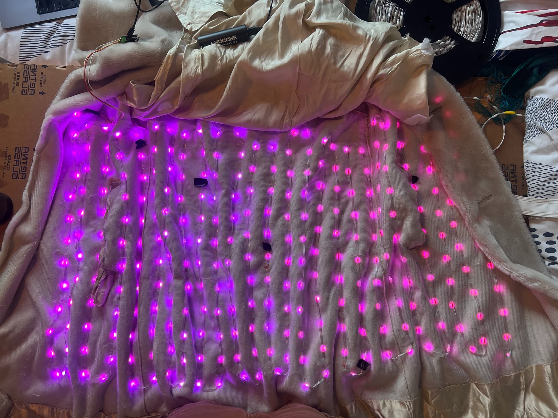
- Glue strings of LEDs in a grid pattern in between the outside and inner lining of your coat.
- Map the LEDs as a 2-D grid.
- Experiment with 2-D patterns.
- Power the whole thing off a 5v USB battery pack.
A full tutorial from start to finish:
-
Find a coat with an inner lining, a white exterior, and an inner breast pocket. You’ll be diffusing the LEDs through the coat. Carefully seam-rip open the lining to add the LEDs, and add a pass-through hole for the wires between the inner jacket pocket and the lining.
-
Set up the PixelBlaze, solder the screw terminals to your PixelBlaze v3. Then “tin” (apply a bit of solder to) the ends of your wires you’re going to screw into the PixelBlaze. Any cheap soldering iron can work for this (but this is a nice one I own), as can basically any solder. For this, leaded solder is easier to work with than lead-free solder. Bonus: Consider a 3-D printed case for the PixelBlaze to make it more durable.
-
Use a standard 5v USB cell phone charger battery pack that has an on-off button and can output 2.1 amps at 5 volts. This is your power source for the project – LiPo batteries are harder to work with and AA battery packs don’t have enough juice. Note that the button to turn a 5v battery pack on and off can — or often is — badly designed; test it. My coat is running off this pack; 5000 mah at 3.7v = 3700 mah at 5v and in testing it lasted from Sunset to 2 AM clamped to 40% max brightness or so, with patterns that don’t turn on a lot of LEDs at once. A USB Power Tester will help you here — try to keep your power draw under 1.0a at 5v.
-
Attach initial wires to your LEDs. Self-Solder Heat Shrink Butt Connectors are amazing for joining two wires without soldering. To use them, you’ll need a heat gun. Use some basic 22 gauge, silicon-coated, stranded electronics wire, in 3 colors, one of which is red. (It can all be one color, but it’s really helpful to have your positive (hot) wire be red, so you don’t accidently fry anything by mis-wiring it. Convention is Black or White for the ground, and then a non-red color for the data. (and a 4th color for the clock, if you have a clock line).
-
Test! Power everything, run a test pattern, check the LEDs are working.
-
Lay out your LEDs in 2D zig-zag grid pattern inside the coat. LEDs on waterproof strands are the way to go. Skip the fragile wires without a full coating, skip the strips of LEDs. This is a product that’s MUCH cheaper on Alibaba Express than domestic suppliers, with better selection. Someone else on this forum recommended these which I used in this project, with the 5 cm pitch, from Ray Wu’s store, who’s well known in this community, and I love it. I’m testing these on a future project. This is findable on both Amazon and on Adafruit, in smaller amounts, for example this. Avoid strings that are just epoxy coated bare wires, not fully weatherized silicon coated wires; the coating will wear off and you’ll get shorts.
-
Add heat shrink tubing at any connection point or strain point, including on top of joints made from the self-soldering tubes, and use the heat gun to shrink it.
-
Test! Power everything, run a test pattern, check the LEDs are working.
-
Attach your LEDs to the inside of the outer layer of the coat with hot glue. Get a decent hot glue gun that has a high and low temp setting, and nice / name brand hot glue sticks. Pay careful attention to not cause them to “pull” at the armpits, sides, etc – anywhere there might be strain. You don’t want or need to glue every LED, because that’ll cause issues with strain relief — just enough to keep them lined up the way you want.
-
Test! Power everything, run a test pattern, check the LEDs are working.
-
Map the LEDs; Take a photo of your LEDs, on, wired up, and use the amazing 2d mapper web app to create a 2d map of them. Note, you may need to invert, rotate, etc your photo first. I’m using 290 LEDs in this project. Pixels
-
Insert the map into the Mapper tab of the LEDs, and remember to hit Save.
-
Program with whatever patterns you’d like. Note that many 2D patterns have scale issues where they don’t look great with fewer pixels, further spread apart. Play around and experiment. To my taste, most patterns available are too “busy” or rainbow-y, and are better with slower animations and fewer colors. To me, this is what separates “ok” from “great” projects — and the new palette functionality can make any existing pattern look totally new.
-
Conserve power. Start by clamping the max brightness (and thus max power) to 60% or so, because the perceptual brightness doesn’t require pushing the full power through the project. Focus on patterns that don’t light up the entire project at once with white hued colors. You need less brightness than you’d think, almost always.
-
Get ready for the real world. Make sure all your wires are tucked away, re-attach the lining of the coat, set up the PixelBlaze to be its own WiFi network so you can control patterns and brightness on the go, have a wonderful time.
And a second video, with a different pattern to finish this off:
(Also in the Instagram post)
Finally – a few thank yous: @Sunandmooncouture creates works of wearable art I can only dream of. This is inspired by this project of theirs: https://www.instagram.com/p/CplwLwftdZi/?hl=en and they gave me advice on what LEDs to use. @zranger1 solved my problems with how to use Palettes in novel ways, in the thread linked above and created a whole new Pattern template for all of us. @wizard for rolling out Palettes, which inspired some of this project.
– Zachary Reiss-Davis (@ZacharyRD), June 2023.