hi all im super new to Pixelblaze. what id like to achieve…i have 3 x 144 pixel strips. each 144 strip i want to split into 3 segments showing different patterns. for example first segment is 22 pixels next segment is 100 pixels and 3rd segment is 22 pixels. so effectively i want to create 3 matrixes of 22 pixels 3x 100 and 3x 22. over 3 strips. how can i achieve this. thankyou all for your hep
So by default, PB doesn’t have ‘segments’, it has one pattern for all the pixels.
That said, there is both a multi-pattern pattern you can use to do the above, as well as the ‘multi-map’ approach I wrote.
You mught want to flesh this out, maybe post a diagram of what you want to do. Lots of ways to do it: 3 separate strips with 3 ‘segments’ each, 1 long strip with 3 segments, or with 9 segments…
Power injection will be needed, as well.
Happy to help you figure it out, but to be clear, the above is non-trivial, so expect to learn how it all works, and to port whatever patterns you like into your own custom pattern.
2 Likes
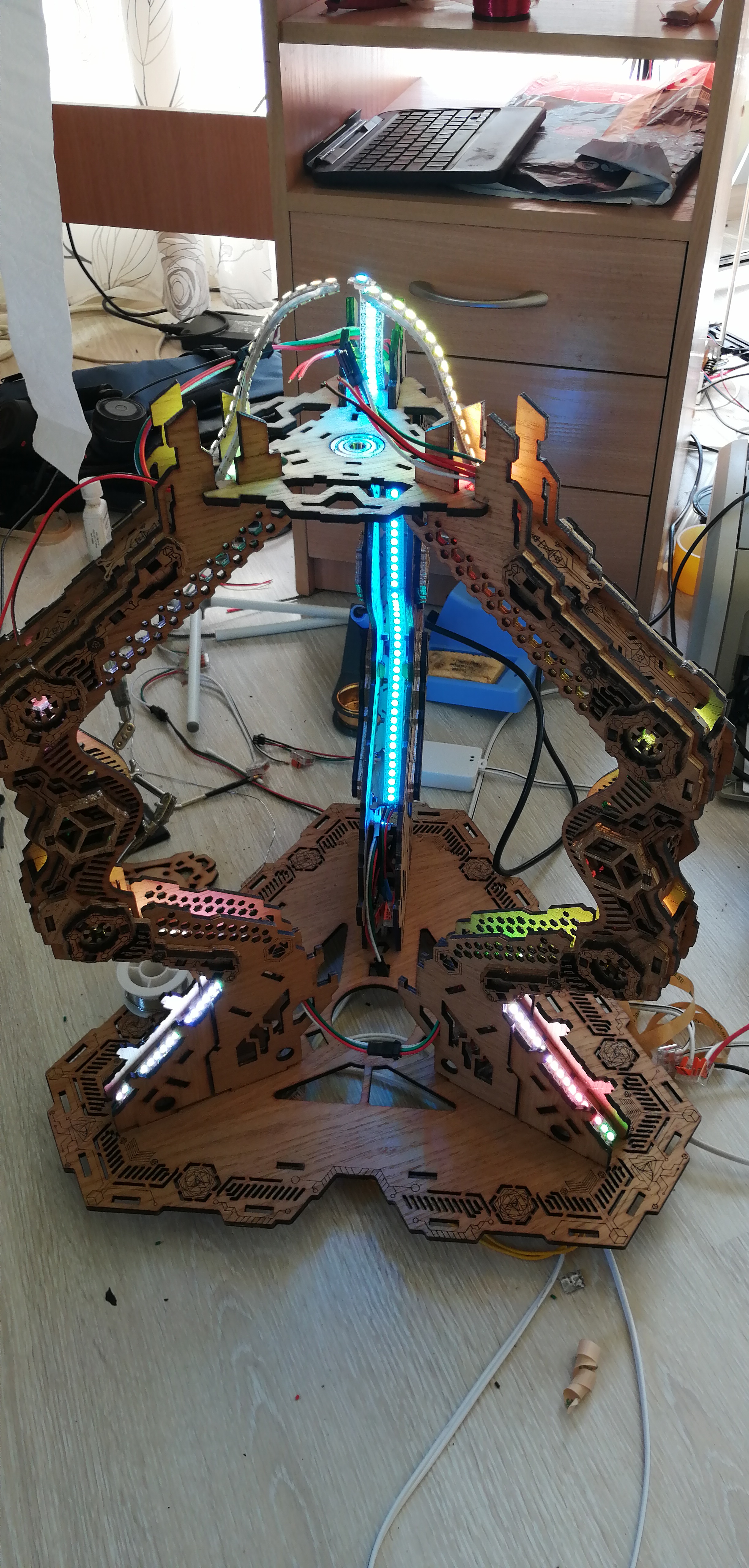
thanks for the infos, i will draw out my pixel map i hope tp achieve…ive worked with led pixels for many years but never thru such programming…generally ive used mapio or madrix to map out piels for stage lighting. now im building small standalone light sculptures which i need to map.
1 Like
hmmm so im trying to upload a pdf image of the mapping requirments but since im a new user the systems not allowing me 
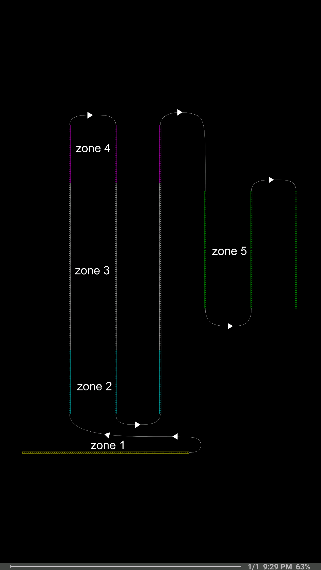
heres a link to the map drawing
https://drive.google.com/file/d/1XGU_NPqkOushwDO1nMaQ63WJjZzk-utT/view?usp=sharing
1 Like
Good map. I’d say you’d likely find my multimap work useful. You can define one big map and then slice it into your desired sections. Could be 2D or even 3D, if that matters.
My example code is hopefully readable, but let me know if something isn’t clear enough. And of course, it depends largely on what patterns you want to do. (@zranger1 's multisegment code has ported versions of many common patterns)
i am a super noobe and im not sure where to start with the code… what defines how many pixels in each map, and how would i specifiy the pixels in zone 2 or 3 or 4 ect and miss the rest tht are between each zone…this is melting my brain currently… 

1 Like
So once you map things, everything is renornmalized to 0…1 in each direction
So if you do (example), the top most left pixel is 0,0 and the bottom most right most is 100,100, it’ll change everything so it’s from 0,0 to 1,1 (often not quite 1,1)
In your case, without knowing the real world, I’d guess that it’ll be 0,0 on bottom left and 1,1 on top right to make sense.
You can build a map from your document using @wizard 's handy 2D photo mapper
However, you might want a 3D map at some point, but Start with 2D please. Much easier.
So now all of the pixels are someplace between 0…1 in each dimension.
If you think about it, if height is one dimension, and width the other (aka Y and X) you could define a section as “between A and B on the Y, and C and D on the X.”
You’ll have to experiment to find your exact values. Do one section at a time.
My example is pretty overloaded… Multiple patterns and multiple definitions (including some changing ones, over time) of different spots.
You can start really simple with a single basic pattern and figure out your section numbers.
Take a 2D pattern, and make sure it ALL lights up at first. That’ll help you ensure you got it wired right and mapped as expected.
Come back once you have that working (post a photo, that’ll help too) and by then, I’ll have a more basic framework version posted (with minimal code, basic math, and boring patterns) you can grow from there. My example was proof of concept and it’s absolutely an advanced example. But the core concept isn’t hard.
wow ok cool, i will try figure out some of this…im totally new to coding… the x,y makes sense just need to now figure out whats what and where ect…
1 Like
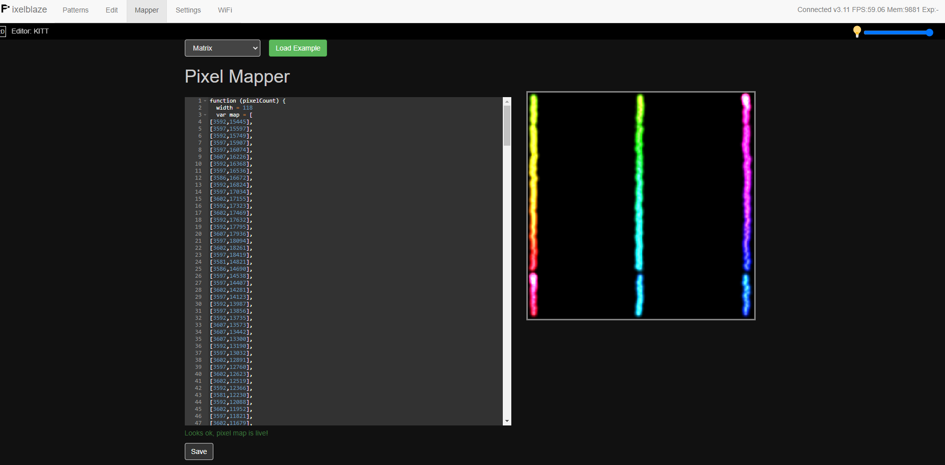
hi, so i have the pixel map data, and ive inputted it into the mapping tab. which shows me my map… but now what…is the pattern in the mapping tab supposed to display on my pixels? it doesnt… so now how do i implement my pixel map with a pattern… this is where im currently stuck… ive been looking at the ‘multi-map ’ approach but im not making sense of it currently. in the mapping page i have this
function (pixelCount) {
width = 15
var map = [
[1143,11999],
[1735,12026],
[2265,12036],
[2873,12020],
[3455,12031],
[4048,12010],
[4619,12005],
[5191,12015],
[5118,8784],
[4263,8648],
[3550,8244],
[3004,7651],
[2700,6865],
[2695,6015],
[2957,5207],
[3497,4599],
[4210,4148],
[5034,3980],
[5873,4127],
[6602,4541],
[7142,5171],
[7446,5952],
[7451,6807],
[7168,7562],
[6628,8228],
[5920,8664],
[5794,12015],
[6366,12010],
[6943,12015],
[7525,12015],
[8086,12036],
[8684,12015],
[9281,12020]
]
for (i = 0; i < pixelCount; i++) {
y = Math.floor(i / width)
x = i % width
// x = y % 2 == 1 ? width - 1 - x : x //zigzag
map.push([x, y])
}
return map
}
which shows me my map but now how do i get the patterns to work with it?
Hi Rich!
The mapper tab will show you a preview of how it comprehends your map, but it doesn’t play a specific pattern through your LEDs. To verify your map on your LEDs, you’ll want to play a 2D pattern and verify it looks as expected. Pixelblaze comes with a pattern called “Utility: Mapping helper 2D/3D” which can help you verify your map. When your map is correct, it should look like this (focus on the matrix on the left, that’s the 2D output):

Also, if you haven’t seen this yet, I wanted to make sure you understand mapping basics in Pixelblaze before we move on to the multimap concept.
The map code you pasted in has 33 statically defined X,Y positions (with very large integers), then adds a traditional 15-wide matrix generator. When everything is rescaled down to 0..1 world units, that matrix will be very compressed, and the last (pixelCount-33) mapped positions LEDs won’t be used. I know that might not make a lot of sense yet until you understand the mapper docs and think through the code you pasted above.
I want to help you get a traditional single map going through the mapper first, and then we can move on to the multi-map concept. Multi-maps (3 logical matrices) will happen in your pattern code, and not via what we define in the mapping tab. The mapping tab is usually a single definition of where each LED is in physical space.
Going off your original project description, I’m envisioning 3 strips of 144 LEDs wired in a zig-zag.
Since you’ll have a total of 144 * 3 = 432 pixels, note that wherever you see pixelCount in mapper or pattern code, that variable will be set to 432 unless you overwrite it.
The basic “Matrix” example map, modified to be 3 rows of 144 columns, should probably be the map defined in your mapper tab:
function (pixelCount) {
  width = 144
  var map = []
  for (i = 0; i < pixelCount; i++) {
    y = Math.floor(i / width)
    x = i % width
    x = y % 2 == 1 ? width - 1 - x : x //zigzag
    map.push([x, y])
  }
  return map
}
Remember to hit “Save” at the bottom.
I’m assuming you wired the 3 strips zig-zag style. If not, you’d comment out the zip-zag line like you already did in the code you pasted in.
Since this is a very wide physical setup, a lot of 2D code will look squished at first. We can practice writing 2D code on your install first by thinking through how to convert any 1D pattern into running in 2D mode. Take any 1D pattern you like, here’s how to convert it. Let’s start with any that do NOT use an array, like block reflections. to convert this to use your new basic map, we need to take the 1D renderer and create a 2D version. Find the 1D:
export function render(index) {
  // `pixelCount` will be set to whatever the pixel count is in the Settings tab - 432 for you
  // `index` will be from 0 to pixelCount - 1

  // (All other pattern code is here)
The map you’ve defined in the mapper tab will only be used if there’s a render2D(index, x, y) {} function found. Make one of these that just uses the 1D version, but using the x position from 0..1 converted to an x pixel index from 0..143:
export function render2D(index, x, y) {
  // Call normal 1D render with 0..1 x converted to a 0..143 pixel `index`
  render(floor(x * 144))
}

export function render(index) {
  // `pixelCount` will be set to whatever the pixel count is in the Settings tab - 432 for you
  // HOWEVER now we want to overwrite it to be 144, since that's how wide the 3 strips are.
  pixelCount = 144

  // (All other pattern code is here)
OK - and if that worked, let’s do one more 1D->2D conversion, this time for a pattern that uses arrays. Here’s “blinkfade” without comments:
Click to expand original code
values = array(pixelCount)
hues = array(pixelCount)

export function beforeRender(delta) {
  for (i = 0; i < pixelCount; i++) {
  	values[i] -= .005 * delta * .1

  	if (values[i] <= 0) {
  	  values[i] = random(1)
  	  hues[i] = time(4.6 / 65.536) + 0.2 * triangle(i / pixelCount)
  	}
  }
}

export function render(index) {
  h = hues[index]
  v = values[index]
  v = v * v
  hsv(h, 1, v)
}
And here it is converted to collapse your 2D map into a 3X 1D renderer. Notice the 3 places I’ve overridden pixelCount: Globally, in beforeRender(), and render().
Click to expand modified code
pixelCount = 144 // New for this 1D->2D conversion
values = array(pixelCount)
hues = array(pixelCount)

export function beforeRender(delta) {
  pixelCount = 144 // New for this 1D->2D conversion
  for (i = 0; i < pixelCount; i++) {
  	values[i] -= .005 * delta * .1

  	if (values[i] <= 0) {
  	  values[i] = random(1)
  	  hues[i] = time(4.6 / 65.536) + 0.2 * triangle(i / pixelCount)
  	}
  }
}

// New for this 1D->2D conversion
export function render2D(index, x, y) {
  // Call normal 1D render with 0..1 x converted to a 0..143 pixel index
  render(floor(x * 144))
}

export function render(index) {
  pixelCount = 144 // New for this 1D->2D conversion
  h = hues[index]
  v = values[index]
  v = v * v
  hsv(h, 1, v)
}
If all this is sinking in and feeling good, I think you’ll be in a good spot to take on the multi-map code!
2 Likes
Nice write up. Good explanation.
I did recommend using the photo mapper because according to his doc above, it’s not just three rows of 144. But that’s a good start.
We have a lot of people who don’t understand how the mapper works, and worse, expect to see their current pattern on the mapper display instead of the rainbow runthru it displays. Maybe @wizard can clarify the UI a bit, to avoid people thinking this?
I haven’t had a chance to simplify the multimapper yet, but will try to get to it in the next day or so. Right now, the example code does a lot. The “simple version” will do a bare minimum:
Define two submaps - one is a basic math limit like x<.5 and y<.5 (so one quarter of the map) and the other is a circle-y spot. And it defines just two patterns to display, one is trivial like a blink, the other is blink with some x/y influence. So it’ll be pretty clear how it works, I hope.
[edit - now added, code in pattern library, and also here]
1 Like
I’d still suggest using the photo mapper (yes, you’ll have to click on each pixel, all 432 of them)
[Actually you could cheat, and map just the ends, take the data it generates, and then do the math for all of the middle bits.]
But yes, this could be mathematically mapped, the way that @jeff explained…
Map the bottom section, then the three columns, the other three columns.
1 Like
ok im really trying to get my head round this and so far i havnt been able to make the map work in any 2d pattern, so i know im not getting it…
this makes sense…
function (pixelCount) {
width = 144
var map = []
for (i = 0; i < pixelCount; i++) {
y = Math.floor(i / width)
x = i % width
x = y % 2 == 1 ? width - 1 - x : x //zigzag
map.push([x, y])
}
return map
}
i have wired in zigzag mode and have taken out the comments just before zigzag but that doesnt work so im missing something to use this properly.
i have used the pixel map tool, and clicked every position to give me the coordinates. however i still dont understand where exactly i place those coordinates and how to change them to betweeen 0…1. this is not currently making sense. ahhh
by the way, my pixel count ha changed to 3 strips of 118 which i have changed in the settings to the correct amount.

Ok, deep breath…
Let The PB worry about the 0…1 conversion.
If you give PB values like 1, 2, 3… It’ll auto renormalize to 0…1, so your values will be stored in the map as 0, .5, 1 (for example, not exactly true but close enough)
The photo mapper gives you a cut and paste map, no extra code needed. Just paste into the mapper tab textarea and save. Unlike the rest of PB, it’s a real JS textarea, that expects a return of a array of values for the map. The photo mapper gives you a direct array of values (and the wrapper code)
When you use code, again, it’s real JS, not PB JSish code, and your code needs to return a set of values… Those values dont need to be 0…1, again. They just need to be consistent.
i tried to make this a 2d pattern to use the map
 export function beforeRender(delta) {
   t1 = time(4 / 65.536) // From 0..1 every 4 seconds
 }

 export function render2D(index, x, y) {


   pulsePosition = t1 * pixelCount // In units of pixels
   distanceFromPulse = abs(pulsePosition - index) // Still in pixels
   // We need something that's high when we're close to the pulse,
   // and low or negative when we're far from the t1 pulse position.
   halfWidth = 5// pixels
   // When proximityToPulse == 5, we're at the pulse, 1 is dim, >= 0 is off
   proximityToPulse = halfWidth - distanceFromPulse
   pctCloseToPulse = proximityToPulse / halfWidth // Now from 1 to 0
   v = clamp(pctCloseToPulse, 0, 1)

   // Or, much more succinctly
   v = max(0, 1 - abs(t1 * pixelCount - index) / 5)

  // Or a third way: 10% of strip width, not 5 pixels
 v = triangle(clamp((index/pixelCount - t1) / 0.2 + 0.5, 0, 1))
   hsv((t1 / 0.1)* 0.2, 1, v * v)
 }
so what i have in the pixel mapper is correct…or i can get rid of all the code and just have the list of coordinates inside the []
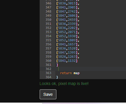
What you posted above is correct: the rainbow runs up the first line, down the second, and up the third. You could likely hand edit the numbers to align it tighter/cleaner… But it looks good.
Run a standard 2D pattern (from the pattern library) and you should see it working well.
Writing your own patterns takes practice, so one step at a time